
Bearings
Use this function to add cross section images of the bearings to the drawing, and calculate bearings’ useful life with a dynamic and a static load. After selecting the function, the menu is opened, in which you can select gearing type, representation, position point, and calculating of useful bearing life.
- Open the Browser
 Browser - Archives.
 - Select Libraries, open the folder Symbols. Open the folder Constants, and select Tool Box.
- Select in the search result Bearings, and select Add.
- Select the draft of the bearing.
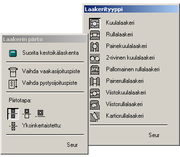
Draft of the Bearing
As a drafting, you can select detailed representation, or a simple representation. Addition to, two other different draft can be selected, which you can select in the simple draft.
Before selecting the bearing type, select as a position point, horizontal position point, or vertical position point. As a lateral position point will be either left / right edge or a center line, when you select the function. As a lateral position point will be either left / right edge or a center line, when you select the function.
To a bearing type, ball bearing, you can also select a gasket. The bearing is added to the drawing as a macro.
- Open Browser. Browser Archives
- Select Libraries, and open the folder Symbols.
- Select under the Constant folder, the Tool Box.
- Select in the search result Bearings, and select Add.
- Select the draft of the bearing.
- Click Next.
- Select the bearing type.
- Click Next.
- Do either of the following:
- Enter the inner and out side diameter, and the values of width.
- If you leave fields empty, you can select values of the variabled bearing classes.
- Select the positioning auxiliary function.
- Select the location in the drawing.
- Select Confirm.