
Edit Constraint
Dialog Box Options
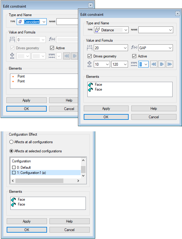
- Type
- The type selected for the constraint. You can change the constraint’s type from the drop down list. Change Constraint's TypeNote:
- The program will not prevent you from making unfit selections. Make sure, that the type you select can be solved for the selected elements.
- You can also change the constraint's elements so that they fit the selected constraint type.
- Name
- You can name the element to make it easier to identify it on the list. From the drop-down list you can select previously entered names.
- Value
- Defines the value of the distance, angle, or radius, depending on which constraint type you are defining. This is a numerical value and it must be greater than 0. You can also enter the value as a numeric calculation, such as 360/8. The calculations available are the same as those in the Formula field.
- Formula
- Defines a variable or an expression for a distance, angle, or radius. Define the Formula Field
- Drives geometry
- When
 Drives geometry is selected, the constraint will function as a geometric constraint that can edit geometry. You can make a constraint a driven dimension by removing the selection
  Drives geometry. A driven dimension can not edit geometry, but variables or expressions can be assigned for it in the Formula field.Note: Driven dimensions defined in a 3D sketch can be used to create customer deliveries with parametric models (requires Vertex Flow). Read more: Vertex Flow Product Documentation
 - Active
- When Active is selected, the constraint is enabled. You can disable the constraint by removing the selection Active. When a constraint is disabled, you can, for example, drag a part fixed with the constraint in an assembly. You can re-enable the constraint by selecting Active again, and the part that was dragged will return to the position defined by the constraint, for example.
- Simulation
- You can simulate a constraint from one of its extreme values to the other. Simulate an Assembly Constraint
- Configuration Effect
- By default the constraint affects all assembly configurations. If an assembly has several configurations, you can select
 Affects at selected configurations, and you can select the configurations that the constraint affects. The (a) in parentheses represents the active configuration. Select all configurations with the selection Select all.
 - Elements
- The elements that the constraint affects. You can add, change or delete constraint elements.Note:
- The program will not prevent you from selecting unfit elements. Make sure, that the constraint can be solved for the selected elements.
- You can also change the constraint's type to fit the elements.