
Analyze an Assembly
General
- There are small differences in the items to be analyzed between the part model and the assembly model.
- If you are looking for part model analysis, see Analyze a Part Model.
- You can select, for example, a part with problems from the list of analysis results, in which case the related part is marked in the model window.
- The results of the analysis are listed in a dialog box from which they can be copied, if necessary.
Perform the Analysis
- Select the function Part | Tools |
 Analyze.
- The program opens the dialog box Model Analyzation.
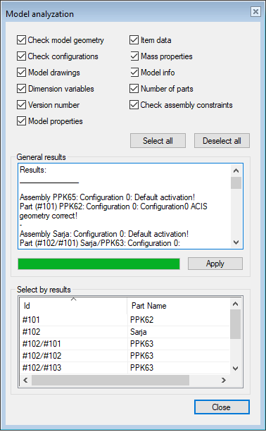
- The program opens the dialog box Model Analyzation.
- Select the objects to be analyzed.
- The Select All button selects all items to be analyzed.
- This should not be used with large assemblies on light grounds as the analysis may take a long time.
- The Deselect All button deselects all items to be analyzed.
- The Select All button selects all items to be analyzed.
- Click Apply.
- The program lists the findings in the dialog box.
- You can browse the list with the scroll bar.
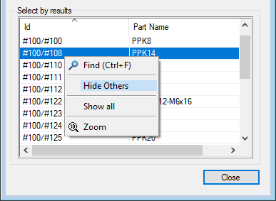
- If necessary, click on the part shown in the list, and the part will be highlighted in the model window as well.
- If necessary, you can hide other parts in the model and leave only the desired part or subassembly visible
- Click the part/subassembly id in the lower box of the dialog box.
- Select the context-sensitive function Hide Others.
- Click Close to exit the analysis function.
- The program marks the part id in red in the feature tree if the part has ACIS errors.
- Fix incorrect parts: Heal the Acis Geometry of a Part Model
Targets of Model Analysis
Checking geometry:
- The program analyzes the status of sketch constraints of the local parts in the assembly and reports under- or over-definitions of a sketch.
- The program also analyzes the flawlessness of the Acis geometry of the configurations in the model.
- Note that the more parts in the model, the longer the analysis will take.
- The program marks the assemblies and parts with incorrect parts in red in the feature tree of the assembly.
Checking configurations:
- The analysis prints the number of configurations and the names of the configurations in the model.
Model drawings:
- The analysis prints the number of drawings and the names of the drawings of the model.
Dimension variables:
- The analysis prints the dimensional variables of the parts.
Version number:
- The analysis tells you which version the model was last saved with and which version it was originally designed with.
- Note: If the model was last saved with a version older than 5.00, the program will report version <5.0.
- Note: If the model was designed with a version older than 15.0.00 (released in September 2008), the program will report version <15.0.
Model properties:
- The analysis tells whether the assembly as a subassembly is frozen or explosive, whether it is added to the assembly parts list, whether it is disassembled into the main assembly parts list, how the symmetry of the part is defined (this is relevant if the assembly is mirrored in the assembly), and whether it is a design automation system.
- The context-sensitive Properties function of the main symbol in the feature tree opens a dialog box where you can change the properties.
Item data:
- The analysis tells you the label or labels and the description of the model item or the lack of an item.
Mass calculation:
- Analyzes the part volume, mass and center of gravity location, and moments of inertia with respect to center of gravity from the active configuration.
- You can get the same information with the Mass function.
Model data:
- The analysis lists the name of each subassembly and part and their named elements and part variables, as well as the label of any guiding part in the assembly. The analysis also tells you if the parts have Acis errors.
- The same report has previously been printed to a file by selecting either the main symbol or a branch from the feature tree and the context-sensitive function: Other Functions > Model data to file.
Number of parts:
- The analysis tells you the number of different parts in the assembly.
Checking assembly constraints
- The analysis looks for under-definitions of the parts and reports as an error if the part has degrees of freedom.
- Note that Vertex G4 does not force you to design an assembly that is fully defined with constraints. If you do not add a sufficient number of constraints to the parts, the parts may move out of place when the assembly is solved.