
Assembly Constraints
Add parts to the assembly model for example from the archives. To specify the position of the parts in relation to each other, you can add constraints to determine and dimension the relationship between the parts.
Free parts with a blue edge line
The parts that require positioning are illustrated differently than others while adding contraints. The software illutrates unconstrained parts by changing the normally black edge line to blue edge line.
Degrees of freedom information
Vertex G4: Software's tip text informs the degrees of freedom, i.e. whether the part is for example sufficiently constrained or underconstrained.
Vertex G4Plant and G4: You can see from the symbols in the assembly tree if the part/subassembly is locked, fully constrained, underconstrained (-) or overconstrained (+).
 Assembly Tree Symbols and Conventions
Allowed degree of freedom means free movement in the degree of freedom's direction. For example, a bolt rotates in a hole or a slider moves parallel to a groove.
Constraint Types
Add constraints between the components to determine their positions in relation to each other. Constraints are defined between the elements of two components. An element can be a face, line or point.
For example, define constraints such as distance and angle dimensions for the parts. These driving dimensions can be used to control the direction and position of the components in relation to each other.
The following geometric constraints can be determined for the parts in an assembly.
- Distance
- Equal distance
- Angle
- Concentric
- Parallel
- Perpendicular
- Coincident
- Tangential
- Symmetrical
- Fix
- Release
You can position the parts in an assembly by using the constraints Concentric and Coincident. The parts will be positioned as follows:
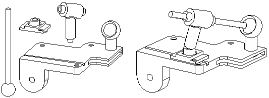
Please note that in order to position a single part correctly and in the correct direction in relation to the other parts, you may need to define more than one constraint for the part. Add a Constraint Between Fixed Parts
Constraint Undo, View, Edit, Delete etc.
Change a constraint to another from the context-sensitive menu.
You can undo the constraint last added before exiting constraint definition. The previous constraint solution is not restored.
The assembly tree shows the geometric constraints defined for the part. When you click a part name in the assembly tree, the geometric constraints affecting that part are displayed in the lower frame of the assembly tree window. You can view, edit and delete the constraints. Assembly Tree
You can fix the unattached constraint to a new element. For example, the constraint can be connected to a face of another part.
You can set the constraint off, and restore again. Disable and Enable Unsolved Constraints of an Assembly
Enter a limitation for the constraint, that it concerns only a specific configuration. Make a Constraint Configuration Specific
Maintain Geometric Constraints
As a default, the constraints determined for the parts in an assembly will be preserved even if the parts are edited afterwards.
If the position of the part is changed by moving it in the assembly, the constraint defined for the part will be preserved. This requires that the element in the part to which the constraint was added remains.
Movie the Parts in an Assembly
After determining all the necessary constraints for a part, the position of the part in relation to the other parts can no longer be changed.
If the structure of the assembly is fixed, so it has no moving parts for example, all parts can be locked in place. This makes the calculation of the geometric constraints of the assembly model easier.
After determining the geometric constraints for an assembly, you can see how the assembly works by pulling a part which free movement in the direction of the X, Y or Z axis or around the axis is allowed.