
Model a Pipeline - Mechanical piping
Piping Design
A pipeline is formed from pipe components, which comprise pipes and pipe parts.
Modeling
A pipeline is modeled in an assembly model. Depending on the extent of the model, the assembly model may contain several pipelines in addition to other geometry. A pipeline can be:
- Main line
- Branch line
The assembly tree contents are easier to manage if the main line and branch line are modeled separately. The assembly structure will also be easier to view.
- Individual pipe assemblies can be easily selected from the assembly tree.
- Components belonging to a pipe assembly can be easily displayed in the assembly tree and working window.
- Assembly tree functions are easy to target to a pipe assembly. For example, hiding or replacing a pipe assembly.
We recommend adding a new pipe assembly with the  Create New function. The assembly will then be automatically defined as a local pipe assembly, and the assembly properties will be set to values suited to a pipe assembly.
A pipe assembly is displayed in the assembly tree just like a local subassembly.
- MainLine (the main line) and BranchLine_1 (the branch line) added to the assembly are local pipe assemblies.
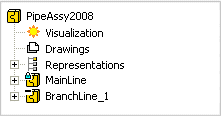
- If the branch line of a pipe assembly is selected for editing, the pipe line components are displayed. The selected item will be the component's label.

Add a Pipeline
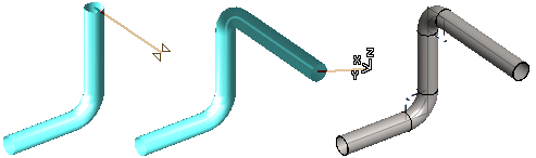
Model a pipeline by sketching the pipe routing.
- Add a pipeline by defining the route of the pipe's centerline by clicking points.
- A pipe component (elbow) or a bending will be automatically added between pipes in places where the pipeline's direction changes.
- Model the pipeline close to the actual dimensions. Modify the dimensions with the dimension table. Refine the pipe lengths and their relative positions using geometric constraints.
- You can also model a pipeline by adding pipes and pipe parts from the component library.
You can continue routing the pipeline from a pipe component.
- Continue the pipeline either as a continuous or jointed pipe.
- Continue the pipeline from a component.
- Continue the pipeline with a set-on.
- Continue the pipeline with a branch component.
- Route automatically.
- A pipeline can end at the following:
- The end of the pipe
- A pipe component
- A branch component
- A set-on

Pipe Components
You can select pipes, pipe parts or hoses from the component library. A piping component can also be a pipe assembly.
You can select library components from the Shared (user's library components) and System (software) folders. The Shared folder will be displayed in the browser after you have saved one of your own components in the library. For example, you can select a cone, elbow, flange, end plate, pipe, T branch or hose from the System folder of the library.
Add a pipe component as follows:
- Add a component to a pipe in the pipeline.
- Add a component while adding a pipeline.
- You can also model a pipeline by adding pipes and pipe parts from the component library.
- You can change the size and material of a pipe component.
Pipe Components and Pipe Assemblies
- You can add piping components or a pipe assembly to an assembly by copying from the model.
- You add a pipe assembly saved in the archive.
 Add Piping Components or a Pipe Assembly by Copying Add a Pipe Assembly from the Archive
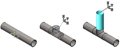
Set-on
Continue the pipeline with a set-on, or set a pipe component on the pipeline.
Set a Pipe Component on a Pipe
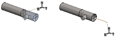
Grip Point Linkage
A grip point linkage is a geometric constraint. In piping design, a handle linkage is created when you add a pipeline or a pipe component, or if you click a point of a pipe or pipe part from the surrounding assembly geometry.
Rotation is a property of a grip point linkage. You can prevent or allow rotation between pipes and pipe parts that belong to a grip point linkage.
Edit a Pipe Component
You can position a pipeline approximately by dragging the pipeline components. This requires that pipeline components have been fixed in position and that component directions have been fixed.
You can change the size and/or material of pipe components.
The relative locations of pipes and pipe sections, and their length in the pipeline, are defined using geometric constraints. You can define precise dimensions for a component by editing the size of a pipe or pipe section in the dimension table.
Move a Pipe Part
You can move a pipe of the pipeline, a bent pipe or a pipe component.
Mirroring of a Pipe Part
You can mirror a bent pipe.
Connect Pipes
Connect pipe ends together.