
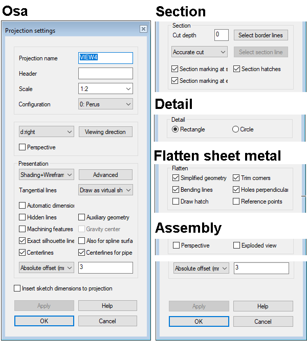
Dialog Box: Projection Settings
General
- The dialog box opens when
- You double-click a projection in a drawing.
- You click the projection and select the context-sensitive function Properties.
- The content of the dialog box differs in some respects, depending on what kind of projection you are dealing with.
- A (normal) projection of a part model drawing.
- A (normal) projection of an assembly model drawing.
- A section view.
- A detail view.
- A flattening projection of a sheet metal part
- Label
- If necessary, you can change the projection label.
- Header
- The header text will be set as the header of the projection.
- Header text is commonly used in detail view and section projections.
- In the section projection, the header is added automatically, based on the section line label, for example A-A.
- For the detail view header, you get the default content when you click on the field, for example DET1
- Edit the header, if necessary.
- The header text is positioned below the projection, but you can drag it to a new location.
- Scale
- If necessary, edit the projection scale.
- Use the preset button to select the scales allowed for the mechanical drawing.
- You can also enter another scale yourself, but we recommend using them only with isometric projections and perspective projections.
 If there is a need to edit the scale of all the projections in the drawing, then edit the properties of the drawing, not the properties of the projections.
- Configuration
- Select the configuration for the part displayed in the projection. If in addition to the basic configuration (0: Configuration) there are also other configurations, select the configuration which is displayed in the projection to the field.
Section views

- Section Depth
- You can edit the section depth value once you have added a section projection in the drawing.
- The default dimension 0 (zero) means that the part is displayed from the point of intersection to the end of the part.
- For example, dimension 1 means that a slice of one millimeter is cut from the part.
- See also: Oblique Section
- Select Border Lines
- Indicate the border lines in the projection, and click Confirm.
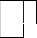
- Select the section line.
- Assign a new cutting line to the section view in the drawing.
- Accurate Cut/Quick Cut
- If you select Accurate Cut, the projection will be cut accurately.
- You can dimension such a projection without any problems.
- Section marking at start
- Select the section mark to be included
 or excluded
  at the beginning of the cutting line.
 - Section hatches
- Select whether to draw section hatches or not .
- Section marking at end
- Select the section mark to be included or excluded at the end of the cutting line.
- Exploded view
- Defines the projection as an exploded view, in which the assembly is displayed as exploded.
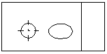
Detail views
 Rectangle
- The shape of the detail view is rectangular.
- The projection can also be shaded or LightWorks shaded.
- Circle
- The shape of the detail view is a circle.
- The projection can only be presented as Wireframe.
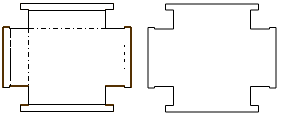
Flattening

- A flatten projection can be produced from a sheet metal part.
- Each model configuration can have its own flattening.
- Drawing Simple Geometry
- A flattening projection will only be created from the geometry of a flattening surface selected from a sheet metal part (default).
- Simple Geometry – A flattening projection will only be created from the geometry of a flattening surface selected from a sheet metal part. Also draws the geometry of the forming feature.
- Simple Geometry - The flattening projection will be created by drawing all geometry lines visible in the viewing direction.
- Trim Corners
-
- The trim corners feature only works for those corners created during modeling, which have not been separately trimmed in the flatten projection.
- If the corners are trimmed separately, the actual geometry is drawn regardless of this selection.
- Corner trimming should only be used for thin sheet materials and such bending methods, where the bending can be done in such a way that curling occurs in the corners of the sheet.
- Trim Corners – The flattening projection is drawn without corner openings.
- Trim Corners – A corner opening is drawn in the flattening projection.

- Bendlines
- Select bend lines to be included or excluded .
- Holes Perpendicular
- In practice: the non-perpendicular hole is converted into a maximum size (oval) hole that must be cut into the sheet in order for the shaft or similar pin to fit diagonally through the plate.
- Holes perpendicular - The hole is drawn in such a size that the shaft still fits through the hole when the sheet is bent.
- Holes Perpendicular – The holes drawn according to the edge lines of the hole.
- Draw hatch
- Select hatches (section hatches) to be included or excluded .
- Reference points
- Select the reference points to be included or excluded .
Drawing mode
- Drawing mode
- The default drawing mode of the projection in a model drawing is wireframe, unless another drawing mode was selected when creating a new drawing for the model. You can also select the drawing mode of a perspective projection in the drawing.
- Advanced
- Available when you have selected the shading or LightWorks drawing mode.
- Advanced settings for shaded drawing modes:
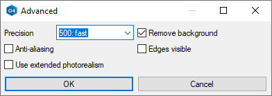
- Select Precision. A greater number is more accurate, but the drawing will also be heavier.
- 500: fast
- 2000: normal. This is usually sufficient for paper prints.
- 4096: best
- Select on or off Remove background.
- Select on or off Anti-aliasing.
- Select on or off Edges visible.
- Select on or off Use extended photorealism.
- Select Precision. A greater number is more accurate, but the drawing will also be heavier.
- Advanced settings for LightWorks drawing modes:
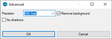
- Select Precision.
- 500: fast
- 2000: normal. This is usually sufficient for paper prints.
- 4096: best
- Select on or off Remove background.
- Select on or off No shadows.
- Select Precision.
- Exact silhouette lines
- The silhouette lines (edge lines) are drawn exactly.
- Coarse drawing speeds up refreshing the projections, but, for example, the dimensioning of an arc will fail.
- If the shape lines of the projection in the drawing are drawn incorrectly, edit the projection and change this selection.
- Note: In assembly drawings, exact silhouettes are not very important, so it is better to clear the setting for them. The update of images showing large assemblies in particular is considerably faster if exact silhouettes are not drawn.
- Also for spline surfaces
- Precise silhouette lines (edge lines) are drawn for the part's spline faces.
- If the shape lines of the projection in the drawing are drawn incorrectly, edit the projection and change this selection.
- Centerlines
- Defines the automatic drawing of centerlines for circles, arcs, sphere and cylinder surfaces.
- Center lines of the arc will be drawn when the arc sector meets the minimum default value: 180 degrees.
- Note: It is not recommended to add centerlines to an assembly drawing, as their generation slows down the updating of large assembly drawings.
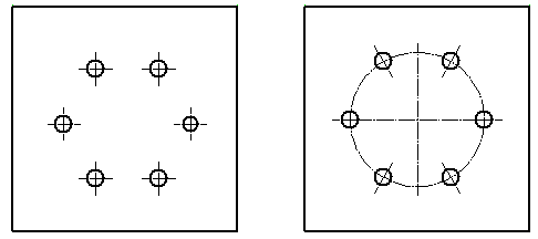
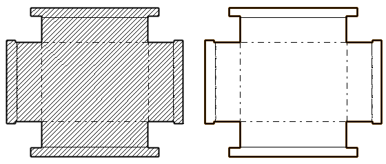
-
- Centerlines is selected on the left.
- Centerlines and Auxiliary geometry are selected on the right.
- (Centerlines) Also for pipe parts
- The centerlines of pipe parts will be visible in the projection.
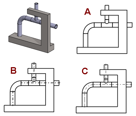
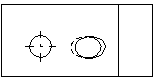
-
- A: No centerlines
- B: Centerlines
- C: Centerlines and Centerlines for pipe parts.
- A:
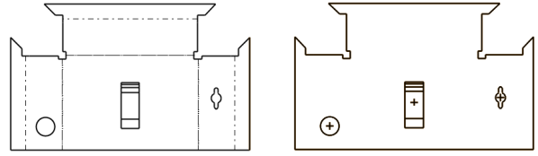
- Auxiliary geometry
- Auxiliary geometry such as guide lines, cross sections, and auxiliary planes are drawn.
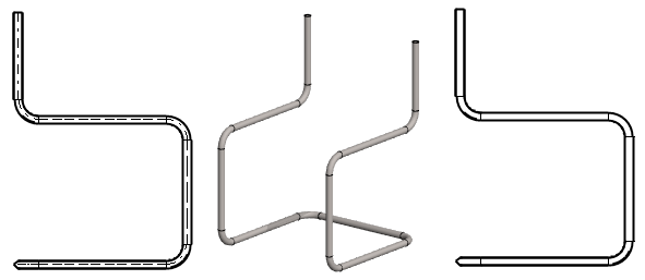
- On the left, the auxiliary geometry is visible and on the right is not.
- Hidden Lines
- The hidden lines are drawn with dashed lines.

- Colored Hidden Lines - You can define the color of the dashed lines being hidden in the Settings.
 Define the Color of Hidden Lines
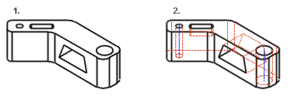
- Machining features
- Machining features are visible if you select Machining features.
- Gravity Center
- Gravity center shows the model's center of gravity in the projection, if the model has a mass calculation.
- Select the gravity center to be included or excluded .
- Update the location of the gravity center by pressing F5 key. If the mass is not up-to-date, it will be updated at the same time.
- You can also delete the lines of the center of gravity by deleting the line, but in this case updating the projection will return them back to view.
- Dimensions can be added to the lines of the gravity center, and when the drawing is updated, the dimensions are also updated.
- You can also draw your own Gravity Center mark.
- Select the gravity center to be included
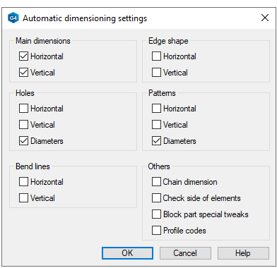
- Automatic dimensioning
- If you select Automatic dimensioning, the Settings button opens next to it.
- Tangential lines
- Apparent shape lines will be created between tangential faces. Select drawing as a shape line or thin line, or disable the drawing of tangential lines in the projection.

- Limit from Model
- With the Limit from Model function, the portion of the 3D model cut off by a cube can be shown in the projection of the drawing.
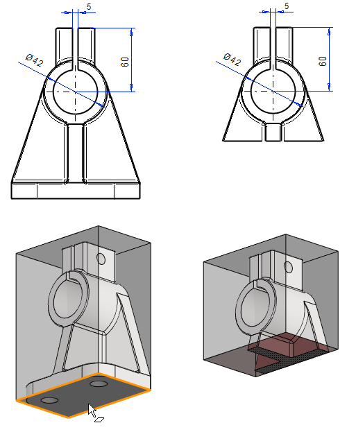
- Double-click the projection in the model drawing.
- Click the Limit from Model button.
- Select the limiting face from the model, and move it with the cursor.
- Click another and etc. face and move the limiting face with the cursor.
- Select Confirm. (Confirm = V key, middle mouse button or the context-sensitive function
 OK.)
OK.)
- Draw Section Hatches
- Draws section hatches defined in the properties of the part on the part to be cut.
-
- Select section hatches to be included or excluded .
- Hatch
- Select section hatches to be included
- Add sketch dimensions to a projection
- With the functions, you can add the dimensions of one sketch to the projection of the part model drawing.