
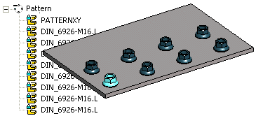
Create a Linear Pattern in Two Directions
General
- You can create a linear pattern both lengthways and widthways by defining the number and length of the elements, or the number and delta (gap between the elements).
- If the part to be patterned is positioned with the Parallel constraint from the base plane of the handle (the xy plane), this same plane is used as the default plane of the pattern when creating the part pattern.
Create a pattern of a part or subassembly
- Use the ribbon bar function when you create a pattern from only one part or subassembly.
- Select the function Assembly | Model |
 Pattern.
 - Select the part or subassembly from which you are creating a pattern.
- An indication of the assembly is worth making a drawing.
- The program opens the dialog box Assembly Pattern Data.
- Select Linear in the dialog box of the assembly pattern.
- Confirm the location: New pattern.
- Enter the number of pattern members in the Number field in both directions
- Length-direction and
- Width-direction
- Enter either
- The distance of the outermost members of the pattern to the Length field or
- The mutual distance of the pattern members to the Delta field.
- Enter the angle if different from the default angle of 90°.
- The default angle is 90°, i.e. the rows of the pattern are at right angles to each other.
- Select OK.
- An auxiliary part (two lines) is drawn on the cursor.
- If necessary, use the auxiliary menu functions to rotate the direction of the auxiliary part around the X-, Y- or Z-axis, either by 90°, 15° or by the angle you enter. You can also click a new reference point from the auxiliary part.
- Click the location of the auxiliary part.
- Recommendation: Click the position of the auxiliary part from the point of the part to be patterned.
- Note that the position of the auxiliary part does not determine the position of the part pattern.
Create a pattern of selected part or parts
- You should use the context-sensitive function when you create a pattern of several parts at once.
- Select the part or parts from which you wish to create a pattern from the assembly.
- Select the context-sensitive function
 Pattern.
 - See above from step 3.
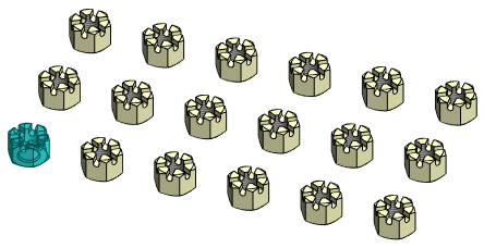
An example of a two-direction linear pattern at a 90° angle
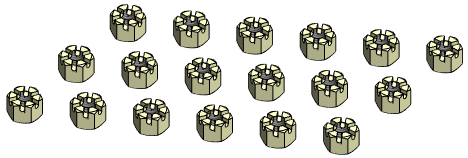
An example of a two-direction linear pattern at a 60° angle
Note:
- You can also create the pattern by defining one direction of the pattern in the dialog box and the second direction by clicking. For example, if you wish to click the lengthways direction (X axis) in the assembly, do as follows:
- At Length-direction, enter only the Number of parts.
- At Width-direction, enter the Number of parts and the Length or Delta.
 Select the Direction of a Linear Pattern in an Assembly
 - When you add the pattern using the New Pattern selection, the program will add the
 PATTERNXY auxiliary part to the pattern. After adding the pattern you can edit the direction and relative positions of the components in the 3D sketch of the auxiliary part.
 - You can use the auxiliary part PATTERNXY for orientating the pattern and assembly constraints to bind the pattern to other parts of the assembly.