Dimension Lines in a Panel Drawing
Framer
You can add different dimension lines to the view of a wall panel drawing. For example:
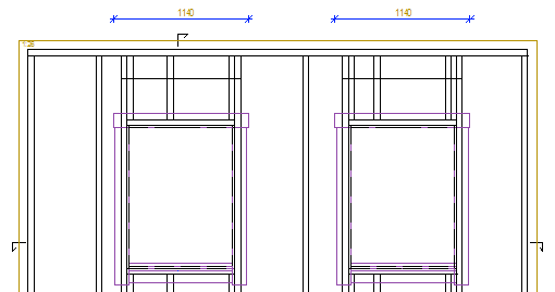
- Main dimension (MAIN) - A dimension line from one edge of the panel to the other, in the specified direction.
- Diagonal dimension, ascending (MAIN_DIAG1) - A dimension line from the bottom left corner of the bottom plate to the top right corner of the top plate.
- Diagonal dimension, descending (MAIN_DIAG2) - A dimension line from the top left corner of the top plate to the bottom right corner of the bottom plate.
- Electrical mounting boxes (ELBOX)
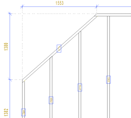
- Top plate length (TOP_PLATE_LEN) - Also the length of an angled top plate.
- Bottom plate length (BOTTOM_PLATE_LEN)
- Top plate pitch (TOP_PLATE_PITCH) - A ratio is the default. If you wish to enter the value in degrees, enter value ANG for the PLATE_PITCH parameter.
- Angled top plate, horizontal/vertical dimensions (TOP_PLATE_ANG)
- Top plate corner points (SHAPE_BY_PIECES) - Dimensions the corner points of a top plate when the parameter PARAMS has the value SHAPE.
-
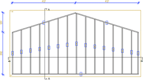
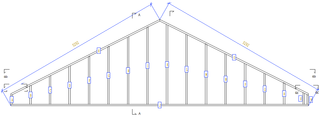
Diagonal dimension of gable panel
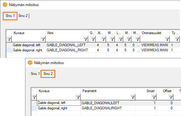
In the dimension line library, you can define a diagonal dimension line for a gable panel from the bottom of the panel to the highest point of the ridge. Set the following additional parameters for the dimension line:- GABLE_DIAGONAL|LEFT
- GABLE_DIAGONAL|RIGHT
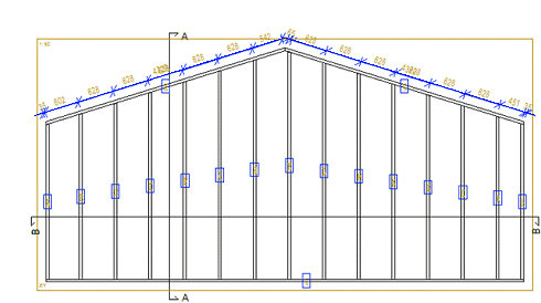
For example:
- Studs in direction of top plate (STUDS_ON_PLATE) - Dimensions the locations of studs in the direction of an angled top plate. The dimension line parameter END can have the value HIGH (top edge) or LOW (bottom edge) according to the side to be dimensioned. If you wish to dimension according to the center of the stud, enter the value MID for the END parameter. The parameter PLATE_SIDE defines if the studs are dimensioned to the top or bottom edge of the top plate. By default, the studs are dimensioned to the top edge, in which case the value of the parameter is TOP. If you wish to dimension the studs to the bottom edge of the top plate, enter BOTTOM as the parameter value. Enter the parameters separated by a vertical bar, for example:
END=HIGH|PLATE_SIDE=BOTTOM
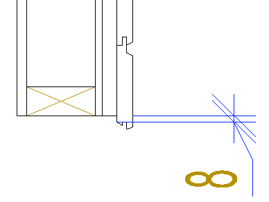
- Reference surface of a cladding boardYou can define the reference surface of a cladding board to be used in dimensioning by using an additional parameter SID~REFSURF for the dimension line.
- When you want to dimension according to the back edge of the profile, the additional parameter is SID~REFSURF=BOT.
- When you want to dimension according to the front edge of the profile, the additional parameter is SID~REFSURF=TOP.
If the reference surface is not determined, the outermost dimensions of the profile are used in the dimensioning.
In the example figure, the siding offset has been dimensioned with respect to the frame. The additional parameter SID~REFSURF=BOT has been used, i.e. the offset is dimensioned according to the back edge of the cladding board.
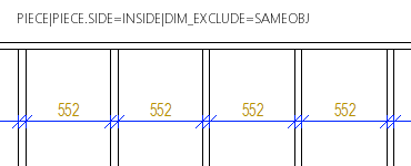
- Dimension between parts
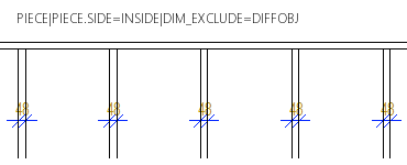
You can dimension the distance between the studs or joists or the insulation between them by setting the additional parameter DIM_EXCLUDE for the dimension line. When the additional parameter is used, part of the dimension line points are filtered out.
For example, the dimension line parameters:- DIM_EXCLUDE= SAMEOBJ - Adjacent dimension points related to the same part are filtered out.
- DIM_EXCLUDE= DIFFOBJ - Adjacent dimension points related to different parts are filtered out.
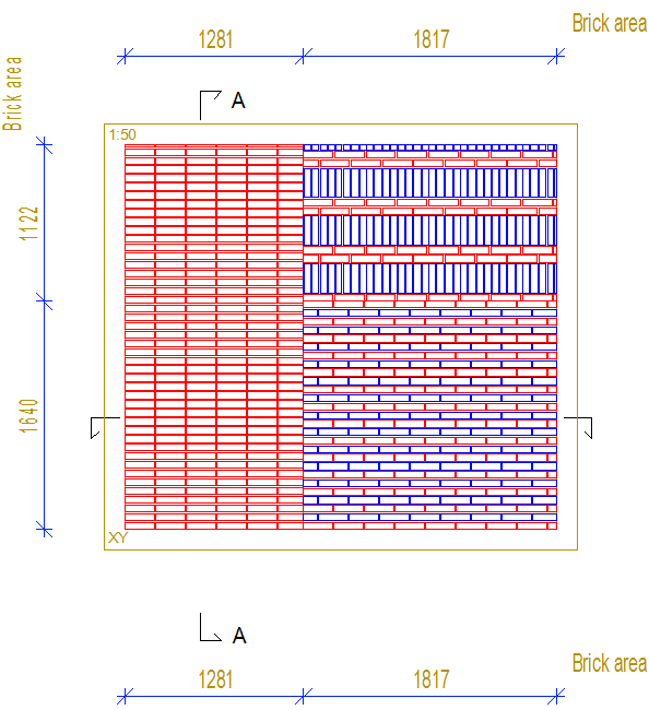
- Dimensions of a clipped layer
When a wall panel layer has been clipped into areas, you can dimension the area limits by setting the dimension line parameter VALUE to ALL. For example, the parameters of the siding layer of a wall panel:
LAYER(1)=SID|SID~LAYER=0+|SID~PART=AREA|SID~NAME=COVER|SID~VALUE=ALL
When VALUE=ALL, all minimum and maximum points for all defined layers are added to the dimension line. COVER type layers on the outside of the frame are dimensioned with the dimension defined above.
- Opening trim dimensions
You can dimension opening trims in a panel drawing view by setting the following parameters for the dimension line:
COMMON_MACRO_SIZE|SPLIT|MLIB=[LIB]|MCODE=[CODE]|MTYPE=[NUM]
Meaning of parameters:
- COMMON_MACRO_SIZE - Dimensioning type (mandatory).
- SPLIT - If the parameter is used, a dimension is added separately for each macro component.
- MLIB - Component library whose components are dimensioned.
- MCODE - Components with this code are dimensioned.
- MTYPE - Macro type of the components to be dimensioned.
- MLIB, MCODE and MTYPE are optional. If none is specified, all components displayed in the view are dimensioned.
You can enter wildcards for the value of the MCODE parameter, such as TRIM_TOP *.
Use of this feature requires that- the trims are selected to be attached to the panel when creating panel breaks and
- the trims are visible in the panel drawing view