
Log Wall Dimensions
Log House Work Drawings
The dimensions and their locations are defined in the LOG_MEAS database. Edit the dimensions in the database view. You can add a dimension in the database by selecting Edit > Add Row Before or Edit > Add Row After from the menu bar of the database view. The tabs of the database view are:
Dimension
Rules
Dimension line parameters
Dimension
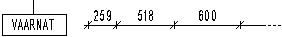
- Label
- Type the dimension line's label text for the log work drawing in the text field.
- Automation
- Select one of the following from the list:
- In Use
- Select one of the following from the list:
- Description
- Type a description text of the dimension in the text field, for example the dimensioned parts.
Rules
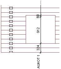
- Rule 1
- Type the horizontal dimension line's distance from the top or bottom edge of the wall in the text field. The positioning of the dimension line above or below the wall is determined as follows:
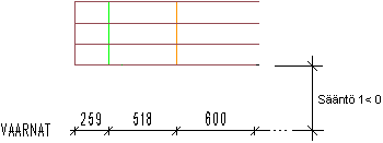
 If a column or some other
element reaches below the lowest log in the log work drawing, the distance of the
dimension line is measured from the lowest element, for example from the bottom of a
column.
If a column or some other
element reaches below the lowest log in the log work drawing, the distance of the
dimension line is measured from the lowest element, for example from the bottom of a
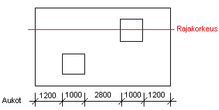
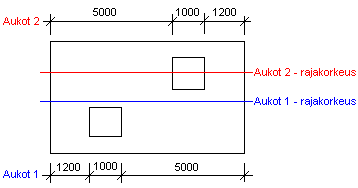
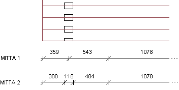
column.- Rule 2
- Type a limit height in the text field. Parts either above or below this limit are dimensioned on the dimension line. If
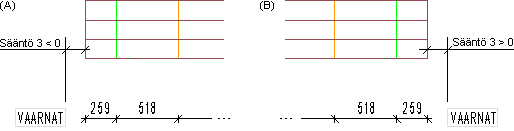
- Rule 3
- Type the horizontal dimension line's label text's location and distance from the top or bottom edge of the wall in the text field.
- Rule 4
- Define the wall parts to be dimensioned by entering their labels in the text field. Separate labels belonging to different parts with commas.
- Rule 5
- Reserved for possible additional parameters.
Dimension line parameters
- Line
- Select a marker line to be drawn from the dimensioned point to the dimension line. The alternatives are:
| 0 | No marker line | |
| 1 | Short marker line 3.5 mm |  |
| 2 | Short marker line 10 mm |  |
- End
- Select the presentation method for the end of the dimension line from the list. The alternatives are:
| 0 | No end |  |
| 1 | Arrowhead |  |
| 2 | Small circle |  |
| 3 | Large circle |  |
| 4 | Dimension line ends at the measurement |  |
| 5 | Slant | |
- Text
- Type the name of a text type defined in the GEOMPROP keyword group in the system settings in the text field. Properties such as layer, pen width, font, color, etc., must be defined for the text. By default, the log work drawing dimension text is LOGFACE.MEAS.
- Label
- Type the name of a text type defined in the GEOMPROP keyword group in the system settings in the text field. Properties such as layer, pen width, font, color, etc., must be defined for the text. By default, the label text of a log work drawing dimension is LOGFACE.MEASLBL.
- Use defaults
- When you want to use the dimensioning settings you defined above, select 0 from the list. You can also select the default values defined for the program by selecting 1 from the list.