
Grip Point Linkage
Piping Design
A grip point linkage is a geometric constraint that binds the parts of a pipe or duct line together. A grip point linkage is created automatically in the following cases.
- Upon the addition of a line in the joint of a pipe/duct and a pipe/duct component.
- Upon the addition of a component in the joint of a pipe/duct and a component.
You can also add a grip point linkage between parts – see Add a Grip Point Linkage. You can view the grip point linkages of a part as follows:
- Select a part or a component.
- Right-click to open the context-sensitive menu.
- Select
 Constraints.
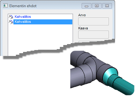
 - Select grip point linkage from the dialog box list. The program will mark the part to be
linked in the model.
- If necessary, you can remove a grip point linkage by selecting Delete.
- If necessary, you can edit a grip point linkage by selecting Edit.
Rotation is a property of a grip point linkage. You can prevent or allow rotation between pipes and pipe parts that belong to a grip point linkage. Fill in a rotation angle value in the dialog box, if you wish to allow the component to rotate around the X, Y or Z axis. Define the rotation using the right-hand rule. The thumb will point in the direction of the axis, and the fingers in the fist will determine the direction of positive rotation.