
Other Dimensioning Settings
Defines the properties of dimension lines and the position of the dimension in the drawing. Define dimensioning properties in the dialog box.
- Select Drafting | Dimensions |
 Dimension >
  Settings.
 - Select the Misc tab.
- Factor for distance between dimensions
- Defines a standard distance at which a new dimension is positioned in relation to another dimension, when that dimension is defined as the position for the new dimension.
- Factor for distance of dimension from line
- Defines a standard distance at which a new dimension is positioned in relation to the dimensioned element when, for example, a point on the dimensioned element is defined as the position for the new dimension.
- Dimensioning tools make constraints
- Vertex G4: Defines a dimension added using the dimensioning function as a constraint when this checkbox is selected. You can edit a geometry by editing a numerical value of a dimension.
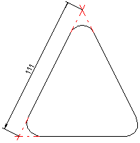
- Automatic leader lines when dimension is added to tangent point (smart dimensioning)
- Defines the adding of extension lines to a tangential point during dimensioning when this checkbox is selected. If the check box is cleared, the extension lines will not be drawn.
- Automatic centering of dimension text
- Defines the dimension to be automatically positioned in the center of the dimension line when this checkbox is selected.
- Automatic centering of dimension text (chain and baseline dimensioning)
- Defines the automatic positioning of dimensions for linear and chain dimensioning after you have selected the position of the first dimension (default). If the check box is cleared, you must position each dimension separately.
- Draw zero to begin (continuous baseline)
- Defines a zero (0) to be drawn at the start of the first dimension in chained linear dimensioning. If the check box is cleared, the zero will not be drawn.
- Delete dimension automatically if connection is lost
- Defines the dimension removed automatically if an element is removed from the geometry to which the dimension was added. If this check box is cleared, this kind of dimension will be retained in the drawing, but it will be highlighted in a different color than default color.
- Ø sign only when needed
- When you add a diameter dimension, a Ø character is added in front of the dimension figure by default. When you enable this setting, the character is not added.