
Line properties dialog box (2D)
Select to the drawing or to the sketch added or line properties selected to edit. Select the line properties in the fields of the dialog box.
Dialog box options
Select the line properties in the fields of the dialog box.
The editable properties depends on the selected elements. If the selected elements have different properties each other, the field is cleared. If you leave the field empty, the elements keep their different properties. If you select a new property in the field, it will affect to all selected elements.

- Layer
- Select the layer on which the line is drawn.
- Pen width
- Select the line width value.
- Line Type
- Select line type. A an example, Continuous, Dashed line.
- Scale
- Select Scale /Gap
- Color
- Select the color by clicking Palette button.
- Bending line
- Select
 Bending
line. Edit the bend properties by selecting the Change
values.
Bending
line. Edit the bend properties by selecting the Change
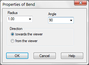
values. - Change values
- Edit values, in the Bend properties dialog box, and select OK.
- Copy
- Click the button, and select in the drawing the line which properties is copied to the line selected to edit.
- Bendline
- Vertex G4: Defines the line as a bend line. Define it´s properties by clicking the Change Values button.
- Fixed
- Defines the line fix in the drawing to a position, in which it is, when the line properties is selected to edit. The fixed line retains it´s position, when geometric constraints are solved.
 Line fix affects only when solving
geometric constraints. The line will remain it´s original position. However, you can edit
the geometry of the line, stretch the line from it's handles or trim, for example.
Line fix affects only when solving
geometric constraints. The line will remain it´s original position. However, you can edit
the geometry of the line, stretch the line from it's handles or trim, for example.- Direction fixed
- Defines the line fixed so that the direction of the line retain, when geometric constraints are solved, but the position of the line can change.
- Constraints
- The geometric constraints defined in the drawing is displayed as a list. Unsolved constraint is highlighted in red color.
- You can stretch or maximize the dialog
box in the vertical direction so that selecting constraints from the list is easier. You
can stretch the upper edge bottom edge of the dialog box. You can maximize the dialog box
to fill the screen from top to bottom with the Maximize
button.
- Apply
- Update edited changes made in the dialog box in the drawing. Geometric constraints of the assembly are resolved.