Model Sketching Mode - Sketching Plane 2D
The working window is activated in the sketching mode for sketching.  Starting a Part Sketch
Activating the Sketching Mode
The sketching plane is activated, when you add a new sketch in the the part. At the same time, you determine the sketching plane in which direction the elements will be drawn.
Activate the sketch mode by the function  New Sketch. For a part with existing geometry, you can select a reference face on the part as the sketching plane. For example, select:
- Line (normal plane)
- Line and point
- Three (3) points plane
The sketching mode will be depicted in the working window by the following:
- Text in the title bar of the working window: Sketching and the label of the part.
If you select Maximize
 in the window, you will see more information of the model on the title bar.
 - Sketching plane: As an example, Horizontal(XY) plane.
- Sketching coordinate system ( axes of X and Y direction), which origin and axes can be used when determining constraints for the sketch.
- Grid (default)
- Drawing functions selected from the toolbar or in the context-sensitive menu.
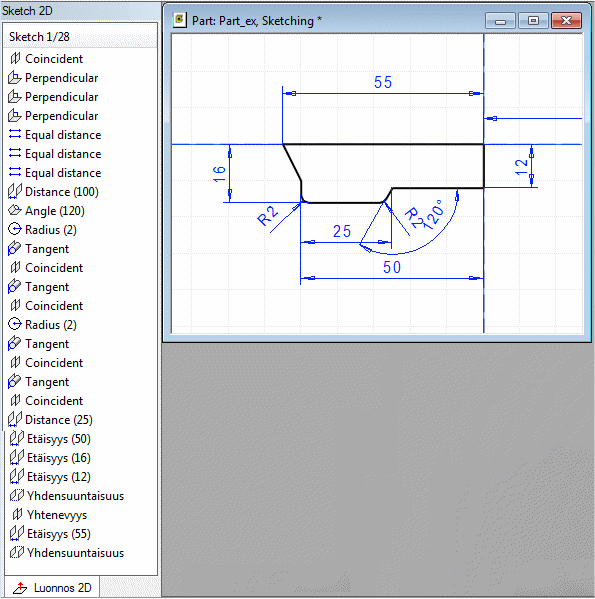
 Draw a Sketch of a Part Model on a Plane
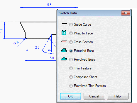
Accepting Finished Sketch
After drawing a sketch, when the sketch is accepted, the operation is selected, and the feature is created based on the sketch.
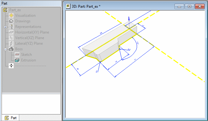
The sketch will be saved in the feature. After specifying the feature, you will exit the sketching mode, and the 3D working window is activated. The part's feature tree will show the feature and sketch as a phase. A part with a volume has been created.
After then, you can continue part modeling using other feature functions. As an example, Round, Draft. You can also add a new sketch on the plane, draw a sketch, and create a new feature based on the sketch.
Editing a Sketch
During modeling, you can return to edit a feature's sketch, if necessary. First select the face formed by the feature on the part, then select the Edit Sketch function.
You can also select the sketch for editing from the feature tree of the part. The sketch will be opened in the sketching mode for editing. In the sketching mode, sketches are always drawn on a plane.
Edit a Model SketchEditing a Feature Sketch
Viewing a Sketch
You can view a sketch as follows:
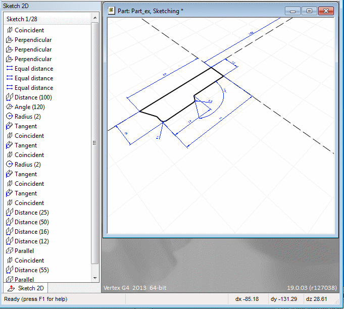
- View and edit the sketch in the XY projection. Select a parallel projection by selecting the context-sensitive function Perpendicular. You can choose to use a rectangular or circular grid. The cursor will automatically snap to points on the grid (default).
 Temporarily, you can prevent the cursor from automatic snapping to points by pressing the Alt key, when drawing a line, for example.
 - You can rotate the sketch by holding down Shift while clicking with the left mouse button, and edit it in the desired projection.
- You can pan the sketch by holding down Shift while clicking with the middle mouse button.
- You can zoom the sketch by moving the mouse while holding down Shift and clicking the right mouse button. Even if you change the view of the sketch during sketching, the elements will be displayed in the sketching plane.
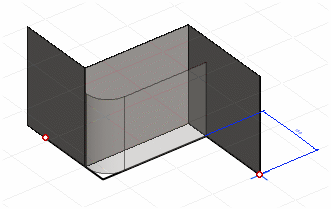
The shape of the part is visible in the sketching mode. The sketching plane is the reference face of the part. The elements are drawn in the direction of the plane.
- You can preview a new sketch and a sketch selected to be edited.
Sketching without the Grid
The grid will be used by default. You can set the grid of by the context-sensitive menu function  Properties. On the dialog box pages Grid and Sketcher you can enable or disable the grid, change the scale of the sketch and choose
  Shaded draft as default.