Draft - Other Planar Face as Reference Surface
You can create a draft in relation to a reference face or a cross section. A plane divides the part. You can define the draft angles of both sides. The positioning of the draft angles is determined by the side from which the plane face is selected.
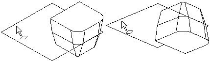
Select the drafted surface, and as the reference layer the help plane top surface. Drafting is performed in both directions with the same angle value.
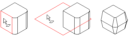
- Select one or more faces to be drafted.
- Select the context-sensitive function
 Draft.
 - Select as the reference plane some of the of the following:
- Face on the plane.
- Face on the cross section.
- Define the draft angle in the dialog box:
- With angle value 0 no draft is created.
- The first angle value determines the draft in the reference face's normal direction (A). In the example, the value of the second angle is 0.
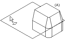

- The second angle value determines the draft in the opposite to normal direction (B) of the same reference face.
- A positive angle value will create a cutout draft (C).
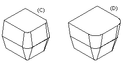
- A negative angle value will create a boss draft (D).
- If necessary, edit the the drafted surfaces or to the reference layer is elected by the dialog box functions.
- Click OK.
Note:
- The draft angles change in the part geometry, when you select as the reference layer the help plane from the opposite side.