
View the Kinematics of an Assembly Following a Line Chain
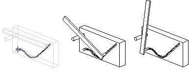
You can model a local guiding part onto an assembly as a guide curve, allowing you to limit the movement of a part between the start and end points of the guide curve. Draw the curve in the 3D sketch as the tangential line chain, which is converted to the spline curve.
Model the guiding part by and large as follows:
- Model the other parts of the assembly as usual.
- Create a local part with which to control the path of movement.
- Add the 3D sketch to the local part and model the tangential line chain as the line chain, along the part is moved. The line chain does not need to be planar.
You can copy the line chain to the 3D sketch, if the line chain is modeled to any part in the assembly.
- Do either of the following:
- Select the context-sensitive Line >
 Tangential Line Chain to a Spline.
 - Select on the toolbar Tangential Line Chain to a Spline.
- Select the context-sensitive Line >
- Select lines to be copied in the 3D sketch.
- Select Confirm, and the guide curve is created.
- Accept the local part.
- Fix the part to be moved onto the guide curve with geometric constraints.
- Move the part with the mouse.