
Define the Reference Constraints for a Part
General
- Parts that are going to be positioned together in an assembly with reference constraints must, as a rule, have constraint sets with the same name so that the constraints of the sets can meet.
- When a part is added to the assembly and a part without a constraint set is specified, the program recognizes the element under the cursor and its shape and tries to create a constraint according to the constraint set.
- This way, for example, the bearing can be placed on the shaft without having to make a constraint set for the shaft.
- There may be several constraint sets in a part.
- Each constraint set in one part or assembly must have a unique name.
Define the Reference Constraints
- In the part’s feature tree, right-click Reference Constraints.
- Select New.
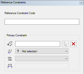
- Enter the Reference Constraint Code.
- The constraint code must be the same for all parts
- Select the Primary Constraint by clicking the arrow button and click an element in the model.
- Select the geometric constraint from the list.
- Select the constraint's direction from the list.
- It is often worth settling for the default direction offered by the program and trying to see if it works.
- If you selected a distance constraint, enter the value of the distance.
- Define the secondary and third constraint in the same way.
Note: The constraints are in mutual order. If a constraint is saved in such a way that the constraint preceding the specified constraint is missing, the constraints are saved in order ignoring the empty constraints.