
Add a Geometric Constraint Between Parts
The constraint can be added between parts in two ways.
- Select the constraint from the ribbon bar and then the elements (surfaces, lines or points) from the parts.
- First select two parts and then the constraint from the context-sensitive menu. In this case, the other parts of the assembly are not included in the selection of elements, and you can only select elements from these two parts.
Select the constraint first
- This method works well when you add the same constraint in succession between several different parts.
- Select | Constraints | eg.
 Add distance constraint.
 - Select the first element.
- Select the second element:
Select the parts first
- This method works well when you enter constraints between two parts and you do not want the cursor to snap to the other parts.
- This allows you to select a hidden surface behind a corner from the part without the cursor snapping to the parts visible in the background.
- This also allows you to add constraints for the parts behind other elements.
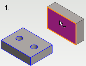
- Select both parts while holding down the Ctrl key.
- Select | Constraints | eg. Add distance constraint.
- The program highlights in blue the part from which the element should be selected.
- Select the first part's element.
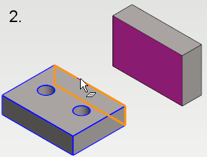
- The program highlights in blue the second part from which the element should be selected.
- Select the second part's element.
Note:
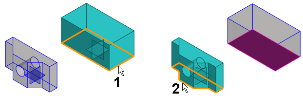
- When adding an assembly constraint like this, the program makes the basic planes of the selected instances visible, and they are selectable if reference geometry is visible. If one or more basic planes of a selected instance are already visible, the hidden basic planes are not made visible.
- Instead of handles, the basic planes are shown when adding assembly constraints like this. Reference geometry must be visible in order for the basic planes to be shown.
- Planes are scaled automatically based on the size of the model. If a plane is visible, it is not scaled when adding constraints. If a plane is too small or too big despite scaling, see the next bullet point.
Note: You can also select elements through surfaces. See Select an Element through a Face
Note:
- Change a constraint to another from the context-sensitive menu.
- When adding constraints, the software illutrates unconstrained parts by changing the normally black edge line to blue edge line. Change the visibility of the edge lines in the graphics settings.