
Dialog Box: New Drawing
The dialog box is opened when you create a new drawing from a part or assembly.
- The number of drawings is unlimited.
- See creating a drawing: New Drawing of a Model
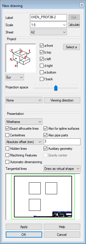
- Label
- The name is entered automatically. As an example, a model whose ID is Ex410Mockup.
- Scale
- Select a suitable scale.
- The program remembers the previously selected scale during the working session.
- The scale is presented for detail views and section views
- Sheet/No sheet
- Select the sheet.
- No Sheet is an alternative.
- Projection
- The default is setting Eur, and the alternative is USA.
- Select the main projections
- Select the main projections
 a: front
- b: top
- etc.


- Flatten sheet metal model
- If a sheet metal part is in the model window and you want a flattening projection for the drawing, select flatten sheet. When you click OK, the properties of flatten drawing are opened.
- flatten sheet
- When the other projections of the drawing have been created, the program opens a dialog box and asks for the properties of the flattening projection Flattening to a Drawing
- Select another projection
- If no other projections are selected, the default is None
- Show the viewing direction from the model
- If you select Viewing direction, the program opens the Viewing Direction dialog box
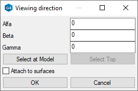
- The option
 Attach to surfaces binds the direction of the projection to the selected face.
 - Perspective
- The option does not affect the main projections.
- Select Perspective, if you want the projection, for example ISO 45 Back Right, displayed as perspective.
- Exploded view
- The option does not affect the main projections.
- Select the Exploded view, if you want the projection, for example ISO 45 Back Right, displayed as exploded.
- Presentation
- The default drawing mode of the projection in a model drawing is wireframe, unless another drawing mode was selected when creating a new drawing for the model. You can also select the drawing mode of a perspective projection in the drawing.
- Advanced settings
- Available when you have selected the shading or LightWorks drawing mode.
- Advanced settings for shaded drawing modes:
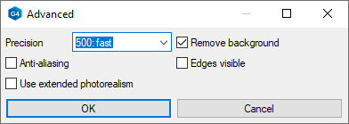
- Select Precision. A greater number is more accurate, but the drawing will also be heavier.
- 500: fast
- 2000: normal. This is usually sufficient for paper prints.
- 4096: best
- Select on or off
 Remove background.
 - Select on or off Anti-aliasing.
- Select on or off Edges visible.
- Select on or off Use extended photorealism.
- Select Precision. A greater number is more accurate, but the drawing will also be heavier.
- Advanced settings for LightWorks drawing modes:
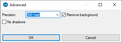
- Select Precision.
- 500: fast
- 2000: normal. This is usually sufficient for paper prints.
- 4096: best
- Select on or off Remove background.
- Select on or off No shadows.
- Select Precision.
- Exact Silhouette Lines
- The silhouette lines (edge lines) are drawn exactly.
- Coarse drawing speeds up refreshing the projections, but, for example, the dimensioning of an arc will fail.
- If the shape lines of the projection in the drawing are drawn incorrectly, edit the projection and change this selection.
 Defaults starting with version 29.0.00 (Vertex 2023).
- In Vertex G4, the part model drawing is done with exact silhouettes by default.
- In Vertex G4, the assembly model drawing is done without the exact silhouettes by default.
- In Vertex G4 plant, both part and assembly model drawings are done without exact silhouettes by default.
- Also for spline surfaces
- Precise silhouette lines (edge lines) are drawn for the part's spline faces.
- If the shape lines of the projection in the drawing are drawn incorrectly, edit the projection and change this selection.
- Centerlines
- Defines the automatic drawing of centerlines for circles, arcs, sphere and cylinder surfaces.
- Center lines of the arc will be drawn when the arc sector meets the minimum default value: 180 degrees.
- It is not recommended to add centerlines to an assembly drawing, as their generation slows down the processing of large assembly drawings.
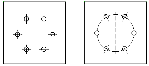
-
- Centerlines is selected on the left.
- Centerlines and Auxiliary geometry are selected on the right.
- (Centerlines) Also for pipe parts
- The centerlines of pipe parts will be visible in the projection.
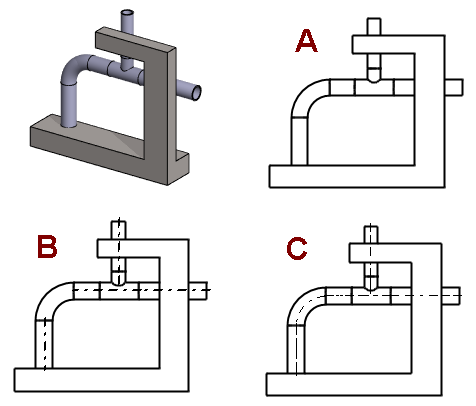
-
- A: No centerlines
- B: Centerlines
- C: Centerlines and Centerlines for pipe parts.
- A:
- Auxiliary geometry
- Auxiliary geometry such as guide lines, cross sections, and auxiliary planes are drawn.
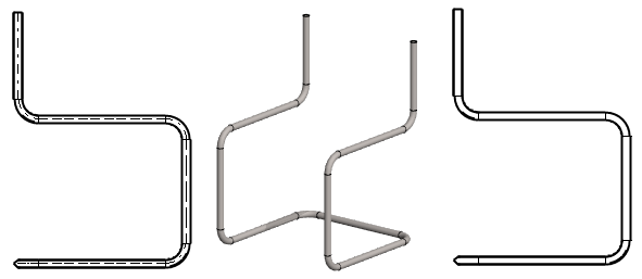
- On the left, the auxiliary geometry is visible and on the right is not.
- Hidden Lines
- The hidden lines are drawn with dashed lines.

- Colored Hidden Lines - You can define the color of the dashed lines being hidden in the Settings.
 Define the Color of Hidden Lines
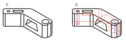
- Machining features
- Machining features are visible if you select Machining features.
- Tangential lines
- Apparent shape lines will be created between tangential faces. Select drawing as a shape line or thin line, or disable the drawing of tangential lines in the projection.

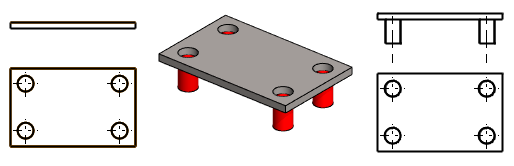
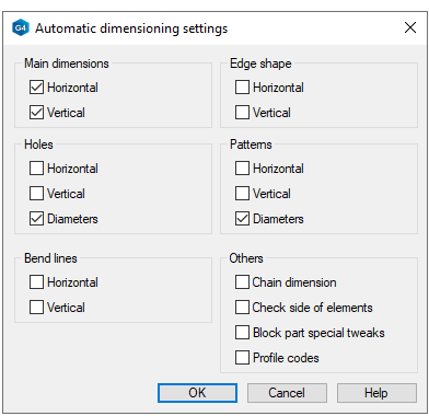
- Automatic dimensioning
- If you select Automatic dimensioning, the Settings button opens next to it.
Note:
- You can add a projection to the model drawing. Select the context-sensitive function Projection in the drawing.
- For more details, see Add a New Projection to a Drawing
- You can edit the projection settings. Select the projection and then select the context-sensitive function Properties.