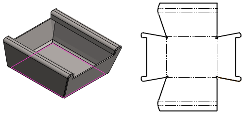
Create a Flattening Drawing
Sheet-Metal Design
General
- If necessary, the flattening of a sheet metal part can be its own projection in the part drawing.
- It is advisable to make an independent drawing of the part with only the flattening projection, if the drawing is exported to the machine tool that cuts the blank in DXF or DWG format.
- In this case, create the drawing on a scale of 1:1.
- Do not add dimensions or form to the drawing.
- If necessary, you can omit bend lines from such a drawing.
- You can also create an independent flattening drawing of the part, to which you can add a form and dimensions to the bending points when the drawing describes the bending.
- In this case, it is also worth adding isometric projections to the drawing, so that the manufacturer can better understand the bending directions.
- In the system settings, different parameters can be set for the bend line when the part bends towards the viewer (BendLine) and when it bends away from the viewer (BendLine2).
- The parameters of other lines related to bending can also be adjusted in the system settings.
- For more details about adjusting the system settings, see Edit Flattening Lines
- Spline surfaces are flattened in relation to the so-called neutral axis starting from version 22.0.03.
- The bends done with older versions are created in accordance with the selected surface.
- If you want to update an old flattening drawing to a new one, you must remove the model's flattening configuration and add the flattening projection to the drawing again.

Starting point
- The sheet metal part model is open in the working window
Create a Flattening Drawing
- If necessary, activate the configuration of the part, which you wish to create a new drawing from.
- Each configuration of a sheet metal part can have its own flattening drawing.
- activate a specific configuration of the model
-
From the tree, select
 Drawings and select the context-sensitive function New Drawing.
 - (OR) Double click
 Drawings in the tree.
- (OR) Double click
- Complete the data in the New Drawing dialog box.
- Select the scale.
- Select the projection
 flatten sheet.
 - Dialog Box: New Drawing
- Select OK.
- The program opens the dialog box Properties of Flatten Drawing.
- Select the properties of the Flattening Projection.
- Select on
 or off
  Draw geometry simply.
 - Select on
 or off
  Show bend lines.
 - Select on
 or off
  Draw hatch.
 - Select on
 or off
  Mark reference points of features.
 - Select on
 or off
  Trim corners.
 - Select on
 or off
  Normal cut holes.
 - See details Dialog Box: Projection Settings.
- Select on
- Select OK.
- The program selects the largest surface from the model and draws it with a highlight color.
- The program asks to accept the surface or to select a new reference surface, in relation to which the flattening will be done.
- Accept or select the surface based on which the flattening will be done.
- Confirm the surface with the Confirm function. (Confirm = V key, middle mouse button or the context-sensitive function
 OK.)
OK.) - Or click another planar surface.
- The program selects the longest edge line from the surface as the direction of the X-axis projection (horizontal direction) and draws it with a highlight color.
- The program prompts you to accept the line or select a new X axis direction line.
- Confirm the surface with the Confirm function. (Confirm = V key, middle mouse button or the context-sensitive function
- Accept or select a surface edge line that determines the X direction of the flattening.
- Confirm the line with the Confirm function. (Confirm = V key, middle mouse button or the context-sensitive function
 OK.)
OK.) - Or click another edge line of the reference surface.
- Confirm the line with the Confirm function. (Confirm = V key, middle mouse button or the context-sensitive function
- If you have selected the parametric program that starts with BendTable or the K-Factor parametric program as the stretch calculation method, complete the data in the Bend Properties dialog box. If not, go to step 11.
- V-Opening. (If BendTable* is selected as the stretch calculation method.)
- Tool Radius (if BendTable* is selected as the stretch calculation method).
- K-Factor. (If K-Factor is selected as the stretch calculation method.)
- You can assign values to all bends at once, or you can select a bend from the list and assign individual values to it.
- Confirm the bend data by clicking OK.
- The program generates the drawing and adds the flattening projection to it.
- The program opens the archive card of the drawing to which it copies the archive data of the model.
- Fill in the archives data of the drawing.
- Select OK.
Note:
- You can edit projection data by selecting the projection and selecting the context-sensitive function
 Properties.
 - If you want to create a section of a flattening projection, remove the selection
 Draw Geometry Simply in the flattening projection properties.
 - You can also add a new flattening projection to an existing drawing. Add a New Projection to a Drawing
