Model a Cross Section Valid for Profile Library
General requirements and comments on the model
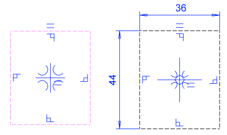
 Create the only sketch of the model To horizontal (XY) plane.
- The origin of the sketch will be the default reference point of the profile feature.
- Add the necessary guide lines, as their endpoints can be used as other reference points when adding the profile.
- Add density to the model to calculate the correct weight for the profiles.
- Add rendering material to the model if you want the profile to look real.
- This is important at least for wooden profiles, such as boards and panels.
- Do not add other features to the model.
- If the model has other features, you cannot save the model to the profile library.
- Do not add a grip point to the model that is otherwise used for library features and components.
- Instead of a grip point, the origin of the model and the direction of the Z axis determine the location of the feature.
Model a profile feature valid for library
- Start creating a new part.
- If you wish to save the part in the archive, enter a label for the part.
- The feature will be named when the profile feature is saved in the library. The name can be different from the part label.
- Select the context-sensitive function
 New Sketch> Horizontal(XY) Plane.
- The origin of the sketch will be the default reference point of the profile feature.
- The normal of the cross section face will be parallel with the Z axis. When modeling a profile part in an assembly, the normal of the cross section will be parallel with the guide curve.

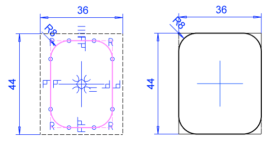
- Draft the sketch of the profile cross section with shape lines.
- The sketch is a closed polyline.
- Draw the web of the profile vertically in the direction of the Y axis.
- Add guide lines in the same sketch for positioning the feature.
- You can select points from the guide line for alternate reference points for the profile feature.
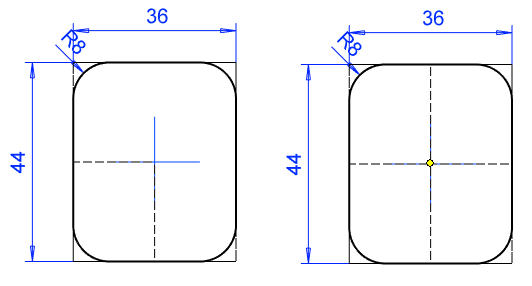
- Add geometric constraints and define variables for the dimension constraints.
- You can test editing the sketch with the Dimension Table function.
- Variables are not required if there is only one cross-section size of the profile.
- Select the context-sensitive
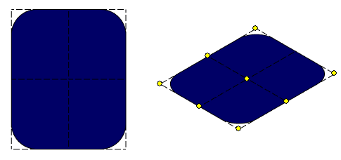
 OK, and select Cross Section as the operation.
 - Add density to the model if the density differs from the default material and you want the weight calculated for the model to be correct.
- Part | Tools |
 Material.
- Select the Mass tab.
- Enter into Density field: Density kg/m3.
- OK.
- Specify the default density: File >
 System Preferences > Mechanical Engineering > Mechanical tab > > Density.
- The default density defined by the software provider is the density of steel: 7850 kg/m3.
- Part | Tools |
- Add rendering material if you want the profile to look real.
- Select the following contextual function: Rendering > Change Material.
- Click Browse
- Browse and select the desired rendering material.
- Select OK to exit the menus.
- Save the cross section to the feature library
- Select the context-sensitive function: Save to Library >As Profile.
- For more details, see: Save a Profile Feature in the Library
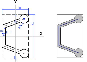
Example of profile cross-section sketching