
Add a Ground Level Line to an Elevation View
You can edit the elevation views generated from the building model by adding a ground level line to the elevation view. In the final elevation drawing, the part of the foundation left under the ground level line can be completely hidden or drawn with a dashed line. This can be accomplished by drawing the line on either of the following layers:
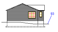
- 93 Dashing ground line
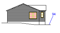
- 94 Clipping ground line
Note: A terrain added to the building model does not form a dashing or clipping ground line. Hide the terrain model from the elevation views by adding it to a hiding group. Check in the drawing generation model settings that visibility by active hiding groups is selected.
Add the ground level line in the following way:
- Open the desired elevation view into a separate drawing window. Use either of the following tools:
- If you haven't created the elevation drawing yet, open the view with the function Update Views.
- Select the view in the Views list box of the dialog box.
- Select the check boxes Update views and Update models.
- Select Drafting as the opening mode of the view.
- If you have already created the elevation drawing and the drawing sheet is open in the workspace, you can open the view with the function Open a View Drawing from a Sheet.
- If you haven't created the elevation drawing yet, open the view with the function Update Views.
- Add the ground level line to the view. Select the Polyline (2D) function.
- Select an appropriate line type on the Properties tab.
- Select the layer on which the line is to be added.
- If you want to display the foundation with a dashed line, select the layer 93 Dashing ground line.
- If you want to hide the part of the foundation left under the ground level line, select the layer 94 Clipping ground line.
- Click the line points.
- Close the drawing window and save the changes.
- If you opened the view from the elevation drawing sheet, close the drawing sheet as well and save the changes.
- Update the elevation drawing with the function Update and Open a Drawing Sheet.
- Select the elevation drawing in the Sheets list box of the dialog box.
- Select the check box Update views.
- You can clear the check box Update models, if you haven't done any changes to the building model after creating the elevation drawing.
Note:
- You can add building height data to an elevation drawing by first opening the elevation view on the drawing sheet by using the function Open a View Drawing from a Sheet, and then adding the height data to the view with the function Add a Height Symbol.
- If you are using the Option System, you can also add the ground level line to a job-specific drawing file. Add the elevation view and the job-specific drawing file on top of each other on the drawing sheet.