
Define a Vertical Section
Architectural, Framer
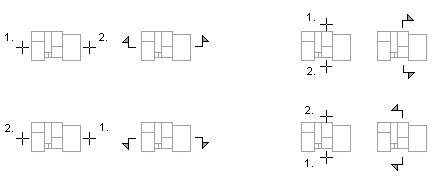
Define a section line in the floor plan for creating a vertical section of a building. The direction of the section is determined by how you click the start and end points of the section line. An arrow indicates the direction of the section when you click the points after the start point. The section line can be a single line or a polyline.
- Activate a drawing window.
- Do one of the following:
- Select Output | Drawings |
 Define Cross Section View.
 - Select the function in the project's document browser:
- Move the cursor on the title Architectural documents / Sections.
- Right-click to open the context-sensitive menu.
- Select Define Cross Section.
- Select Output | Drawings |
- Click the start point of the section line.
- Click the other points of the section line.
- Select Confirm.
- Select the model from which the section will be created. Select one of the following:
- A drawing generation model that is formed by collecting specific objects and drawing-model pairs from the building model. For example Sections.vxm. Forming the drawing generation model can be slow for large models.
- Active architectural model (model.vxm) or Active framing model (framing.vxm), whichever is active. No drawing generation model is created, which speeds up generating the section for large models. Before generating the section, you can hide the model geometry that you do not want to include in the section.
- Type the depth (mm) of the section in the text box. All objects from the generation model that are between the section line and cutting depth are included in the section. With a section depth of 0, all objects that are in the direction of the section from the section line, are included.
- Type the section label in a text box.
- Type the section name in a text box.
- Update the section.

Note:
- Building components, such as cabinets and other furniture, are also truly cut if they are on the section line.
- Update the section using the function Update and Open Section.
- After updating, sections can be added on the drawing sheet with the function Add a Drawing to a Sheet.
- You can quickly generate a section drawing with the function View | 3D View |
 Section View, see Quick Section. The section drawing is created according to the open model file of the building. No section line markings are added in the floor plan drawing.