
Basic Parameters
You can edit the basic parameters of a project as follows:
- Open the project's document browser.
- Right-click
 Settings.
 - Select Edit Project Parameters.
- Select System parameters as the parameter set in the top left corner of the Project Parameters dialog box.
- Edit the parameters.
 Project Parameters Dialog Box
Below is a description of the basic parameters of the template project included in the standard delivery of the software.
| Description | Label | Purpose and possible values |
| Base height of a floor from the zero level. | ZMASTER | Base height defined in the basic parameters is used only, if the height has not been defined in the floor-specific parameters. In the template project included in the standard software delivery, the base height of each floor has been defined in the floor-specific parameters, see Parameters of Different Floors. |
| Room height | ROOM_HEIGHT | Room height defined in the basic parameters is used only, if the parameter has not been defined in the floor-specific parameters. In the template project included in the standard software delivery, the room height on each floor has been defined in the floor-specific parameters, see Parameters of Different Floors. |
Constraint system
| Enables the constraints on object level | CONSTROBJ | Binding building components to each other with geometric constraints is enabled, when the keyword value is YES. Change the keyword value by typing YES or NO in the Value field. |
| Associative walls | BDASSO | When the keyword value is YES, the Associative Walls setting is enabled by default. When the setting is enabled, geometric constraints can be added between walls. Change the keyword value by typing YES or NO in the Value field. See Parametric Building Model - Settings. |
| Automatic floors | AUTOFLOOR | When the keyword value is YES, the Automatic Floors setting is enabled by default. When the setting is enabled, the program automatically adds a floor based on the closed wall chain in the floor plan. The program will automatically generate the floor every time you edit or update the floor plan, for example by moving walls. Change the keyword value by selecting or clearing the check box  . See Parametric Building Model - Settings. . See Parametric Building Model - Settings. |
| Automatic rooms | AUTOROOM | When the keyword value is YES, the Automatic Rooms setting is enabled by default. When the setting is enable, the program will automatically create rooms based on the walls in the floor plan and calculate the floor area. The program will automatically generate them every time you edit or update the floor plan. Change the keyword value by typing YES or NO in the Value field. See Parametric Building Model - Settings. |
Walls
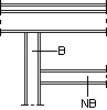
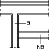
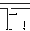
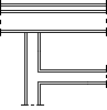
| Wall TEE intersection type | WALL_TEE_TYPE | Determines how a wall T intersection joint is formed. Affects the joints of framed, sheathed walls. May have the following values:
B = bearing wall NB = non-bearing wall |
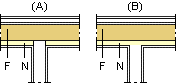
| Wall TEE intersection clip line if type OPEN_ALWAYS | WALL_TEE_CLINE | Determines the cutting line of the frame of a joining wall when the WALL_TEE_TYPE parameter has the value OPEN_ALWAYS. The parameter gets a line depicting a structural layer of the target wall as a value. The meaning of the parameter is described in the example below, in which the exterior wall has additional studs on the inner frame surface. In figure (A) the value of the parameter is INTERIOR, meaning that the cutting line is the inner surface of the exterior wall's frame. In figure (B) the value of the parameter is the inner surface of the additional studs (the name of the line depends on customization).
F = exterior wall frame N = additional studs |
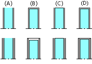
| End cap in free wall end | WALL_END_CAP | Determines whether the end of a free interior wall is capped or not. NO : Wall is not capped (A). YES : Wall is capped (B). If the wall has double sheathing, the thickness of end cap is the total thickness of sheets. SINGLE : A line is added at the end of the wall (C). DOUBLE : Same as YES. A feature to be custom-fitted. SHEET: Wall is capped (D). If the wall has double sheathing, the thickness of end cap is the thickness of outer sheet. If the interior and exterior sheathing are in different thicknesses, the thicker sheet will be used.
You can change the value for a specific wall in the wall properties. If the value is YES, the panel length is determined according to the architectural wall without the end cap.
The parameter adjusts the representation of the wall in the floor plan. In the model, the actual sheet is not added, but the color of the free end surface is set to the same color as the interior surface of the wall. You can disable this feature by setting the following keyword in the user/SETUP file: set.free_end.color= 0 |
| End cap in free wall end | EXTWALL_END_CAP | Determines whether the end of a free exterior wall is capped or not. Has the same options as the parameter WALL_END_CAP. |
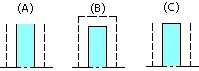
| Presentation of a free foundation wall end | FNDWALL_END_CAP | Determines the presentation of the free end of a foundation wall in a drawing. NO : Lines will not be drawn (A). YES : Two lines will be drawn (B). The lines will be drawn between the following lines: - INTERIOR and EXTERIOR - SIDING and INTERIOR FINISH, or EXTERIOR FOOTER and INTERIOR FOOTER. SINGLE : One line will be drawn between the lines INTERIOR and EXTERIOR (C).
|
| Section drawing figures | SECT_DRWFIG | The lines depicting the structural layers of a wall are drawn in the vertical section created of the 3D model in the same way as in the floor plan of the building. This requires that the AUTOSECTION feature has been selected for the 3D wall volume. |
| Log wall base height | LOG_WALL_B | The height of the lowest point of the bottom log in a log wall in relation to the floor base height. Value defined in the basic parameters is used only, if the parameter has not been defined in the parameters of the 1st floor. |

Windows and Doors
| Vertical framing tolerance for windows | WTOLV | Can be added to either the ROH (opening height) or WTOLV parameter in the window library. Set the value to zero when designing a log house. The installation spaces of openings in a log house are read from the LOGHOUSE setup file. |
| Horizontal framing tolerance of windows | WTOLH | Can be added to either the ROW (opening width) or WTOLH parameter in the window library. Set the value to zero when designing a log house. The installation spaces of openings in a log house are read from the LOGHOUSE setup file. |
| Top edge tolerance of window opening | WTOLT | Can be used as a default value for the WTOLVT parameter (top edge tolerance in the window parameters) in the window library.Added to the top height of the window, if the window has not WTOLV nor WTOLVT parameter. |
| Bottom edge tolerance of window opening | WTOLB | Can be used as a default value for the WTOLVB parameter (bottom edge tolerance in the window parameters) in the window library.Added to the bottom height of the window, if the window has not WTOLV nor WTOLVB parameter. |
| Left edge tolerance for window opening | WTOLL | Can be used as a default value for the WTOLHL parameter (left edge tolerance in the window parameters) in the window library.Added to the left edge of the window, if the window has not WTOLH nor WTOLVL parameter. |
| Right edge tolerance for window opening | WTOLR | Can be used as a default value for the WTOLHR parameter (right edge tolerance in the window parameters) in the window library.Added to the right edge of the window, if the window has not WTOLH nor WTOLVR parameter. |
| Module tolerance | WMODULE | Default value for the Module offset of a window. The property is used to define the frame dimensions of the opening in the horizontal and vertical directions. |
| Vertical framing tolerance for doors | DTOLV | Can be added to either the ROH (opening height) or DTOLV parameter in the door library. Set the value to zero when designing a log house. The installation spaces of openings in a log house are read from the LOGHOUSE setup file. |
| Horizontal framing tolerance for doors | DTOLH | Can be added to either the ROW (opening width) or DTOLH parameter in the door library. Set the value to zero when designing a log house. The installation spaces of openings in a log house are read from the LOGHOUSE setup file. |
| Top edge tolerance for door opening | DTOLT | Can be used as a default value for the DTOLVT parameter (top edge tolerance in the door parameters) in the door library.Added to the top height of the door, if the door has not DTOLV nor DTOLVT parameter. |
| Bottom edge tolerance for door opening | DTOLB | Can be used as a default value for the DTOLVB parameter (bottom edge tolerance in the door parameters) in the door library.Added to the bottom height of the door, if the door has not DTOLV nor DTOLVB parameter. |
| Left edge tolerance for door opening | DTOLL | Can be used as a default value for the DTOLHL parameter (left edge tolerance in the door parameters) in the door library.Added to the left edge of the door, if the door has not DTOLH nor DTOLHL parameter. |
| Right edge tolerance for door opening | DTOLR | Can be used as a default value for the DTOLHR parameter (right edge tolerance in the door parameters) in the door library.Added to the right edge of the door, if the door has not DTOLH nor DTOLHR parameter. |
Floors and Ceilings
| Default roof overhang for inserting eaves line | ROOF_OVERHANG | Is displayed on the status bar, when the Modeling | Floor, Roof |  Roof Roof  Eave Line function is selected. Eave Line function is selected. |
| Default roof locating height | ROOF_HGT_LOC | Determines whether the top or bottom surface of the roof is located in the selected point when adding a roof.1 : The top surface of the roof is located in the selected location.0 : The bottom surface of the roof is located in the selected location. |
| Default roof eave height | ROOF_HEIGHT | The default height of the eaves in relation to the floor base height. |
| Roof tile width | ROOF_TILE_WIDTH | Roof tile width for calculating the number of tiles. |
| Roof tile length | ROOF_TILE_LENGTH | Roof tile length for calculating the overlapping of tiles. |
| Mansard roof hip height from eave | MANSARD_HIP_DZ | Determines the default height of the hip of a mansard roof from the eave. Connected with the function for changing the eave shape of a sketching roof. See Change Gable Type. |
| Floor surface layer thickness | FLR_FR_THCK2 | Floor surface layer thickness. Value defined in the basic parameters is used only, if the parameter has not been defined in the floor-specific parameters. |
| Default floor height | FLOOR_HEIGHT | The default floor height in relation to the floor base height. In the template project included in the standard software delivery, the parameter is calculated with a formula:-#P~FLR_FR_THCK2#In this case, the default height position of a floor is the floor base height - floor surface layer thickness. |
| Default floor locating side | FLOOR_HGT_LOC | Determines whether the top or bottom surface of the floor is located in the selected point when adding a floor.1 : The top surface of the floor is located in the selected location.0 : The bottom surface of the floor is located in the selected location. |
| Default name for floor edge line in wall | FLOOR_EDGE_LINE | Defines the wall line based on which a floor is added, when automatic floors are enabled, or the default reference line, when a floor is added by clicking walls. The parameter value can be the wall's line EXTERIOR (exterior side of frame) or INTERIOR (interior side of frame). Value defined in the basic parameters is used only, if the parameter has not been defined in the floor-specific parameters. |
| Framing area thickness | FORCE_FRM_THICK | The framing area thickness is the same as in the building model created in architectural design. |
| Default ceiling height | CEIL_HEIGHT | The default height of the ceiling in relation to the floor base height. In the template project included in the standard software delivery, the parameter is calculated with a formula:#P~ROOM_HEIGHT#In this case, the default height position of a ceiling is the floor base height + room height.The room height is defined either in the basic parameters or in the floor-specific parameters. |
| Default ceiling locating side | CEIL_HGT_LOC | The default locating height of the ceiling. Determines whether the top or bottom surface of the ceiling is located in the selected point when adding a ceiling.1 : The top surface of the ceiling is located in the selected location.0 : The bottom surface of the ceiling is located in the selected location. |
| Default name for ceiling edge line in wall | CEIL_EDGE_LINE | Default reference line of a ceiling, when it is added by clicking walls. The parameter value can be the wall's line EXTERIOR (exterior side of frame) or INTERIOR (interior side of frame). Value defined in the basic parameters is used only, if the parameter has not been defined in the floor-specific parameters. |
| Default countertop height | CTOP_HEIGHT | The default height of a countertop in relation to floor base height. |
| Default countertop locating side | CTOP_HGT_LOC | Determines whether the top or bottom surface of the countertop is located in the selected point when adding a countertop.1 : The top surface of the countertop is located in the selected location.0 : The bottom surface of the countertop is located in the selected location. |
Add a Section Symbol
| Name of section mark file | SECT_MARK_FILE | The drawing file of the start and end point symbol of section line added with the Output | Drawings |  Define Cross Section View function. Software supplier's drawing file is in the ../system/macros/system folder. Save a customer-specific drawing file in the ../custom/macros/system folder. Define Cross Section View function. Software supplier's drawing file is in the ../system/macros/system folder. Save a customer-specific drawing file in the ../custom/macros/system folder. |
| Line in cross section marking | SECT_LINE | Determines the marking method of the section line.YES : The section line is drawn.NO : The section line is not drawn. |
Calculating panel weight
| Siding weight for panel weight calculation | SIDING_WEIGHT | Siding weight for panel weight calculation. If the siding boards are generated as profiles in the structure model, the weight of the siding is formed by the weight of the individual profiles. In this case, the parameter SIDING_WEIGHT is not taken into account. |
| Door weight for panel weight calculation | DOOR_WEIGHT | Door weight for panel weight calculation (kg/m²). The weights of other openings are defined with the parameter OPENING_WEIGHT (kg/m²). If the DOOR_WEIGHT parameter has not been defined, the system will use the OPENING_WEIGHT parameter for all openings. |
| Opening weight for panel weight calculation | OPENING_WEIGHT | Weight of other openings than doors for panel weight calculation (kg/m²). The door weight is defined with the DOOR_WEIGHT (kg/m²) parameter. If the DOOR_WEIGHT parameter has not been defined, the system will use the OPENING_WEIGHT parameter for all openings. |
Energy Calculation
| The U value of an exterior door unless defined in the library | UVALUE_EXTDOOR | Default U-value, which is used in energy calculation for all exterior doors, if the U-values have not been defined in the door library you are using. |
| The U value of a window unless defined in the library | UVALUE_WINDOW | Default U-value, which is used in energy calculation for all windows, if the U-values have not been defined in the window library you are using. |
| Exterior corner U-value | UVALUE_CRNEXT | Used in energy calculation. |
| Interior corner U-value | UVALUE_CRNINT | Used in energy calculation. |
| U value of joint between base floor and wall | UVALUE_PRMFLR | Used in energy calculation. |
| U value of joint between intermediate floor and wall | UVALUE_PRMFLRINT | Used in energy calculation. |
| U value of joint between ceiling and wall | UVALUE_PRMCLNG | Used in energy calculation. |
| U value of the door perimeter | UVALUE_PRMDOOR | Used in energy calculation. |
| U value of the window perimeter | UVALUE_PRMWIN | Used in energy calculation. |
| North direction | NORTH_ARROW | User defined north direction in degrees measured clockwise from the positive y axis. The north direction is used in energy calculation. |
Misc
| Truss drawing saving location | TRUSSEP_MODE | The saving location of roof truss drawings and the naming system of the drawing files produced with the method used in the software versions 10.0/10.1 and older. 1 : The drawing files are saved in the Trs directory of the project, named with a T at the beginning of the file name and the truss label at the end, for example T.R1.vxp, T.R2.vxp etc. Otherwise the drawing files are saved in the Truss_picts directory of the project, named with a TRUSS at the beginning of the file name and the truss label at the end, for example TRUSS.R1.vxp, TRUSS.R2.vxp, etc. |
| Wall panel shape | WALLPNL_MODE | Determining wall panel shape when classic wall panels are used. 1 : Wall panel shape directly from the shape of the wall (default). 0 : Wall panel shape determined by height macros. |
You can also add the following parameters to the PARAMETERS file by yourself:
| Description | Label | Purpose and possible values |
| Default bottom height of a corner trim | CORNER_TRIM_BOT | Connected with the function for adding corner trims of the default height. |
| Default top height of a corner trim | CORNER_TRIM_TOP | Connected with the function for adding corner trims of the default height. |
| Base height of a railing | RAILING_Z | The base height of a railing. When adding a railing, you can lock the cursor to the base height. |
| Default offset of railing baseline | RAILING_OFFSET | The default offset of the railing baseline from the points selected when adding the railing. |
| Building floor height above sea level | ABOVE_SEA_LEVEL | This parameter is used in terrain modeling and situating the building into the terrain. |
| Aligning the Hatch of an Exterior Siding with a Project-specific Grid | WALL_HATCH_Z[N] "CODE|Z|FORCE" |
[N] is a sequential number starting from 1. When there are several keywords, they must be numbered in order, 1, 2, 3, etc. CODE is the code based on which the exterior siding is searched for. The wildcard characters question mark (?) and asterisk (*) are allowed. The question mark stands for a single character, and the asterisk stands for several characters, for example "BRICK*". Z is the height of the grid origin from the model's absolute origin. FORCE is an optional parameter. It forces the hatch to be aligned with the grid in all exterior sidings matching the search criterion, regardless of whether a hatch origin has been set for the siding or not. If the FORCE parameter is not used in the keyword, the hatch's own origin is used, if one has been set. Otherwise, the hatch will be aligned with the grid. Example: WALL_HATCH_Z1 "BRICK*|20|FORCE" WALL_HATCH_Z2 "SIDING*|0" |