Define an Elevation View
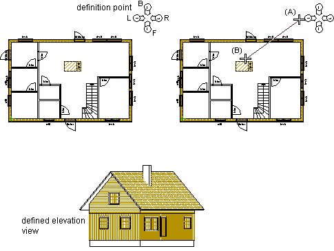
With this function, an elevation view of a building is defined. The view will be an axonometric projection of the building. The labels and directions of existing elevation drawings can be checked from a definition point. The location of the definition point is selected from the 2D drawing (the definition point does not affect the creation of the elevation view). An elevation view is defined by selecting the viewing direction with two points.
- Activate the drawing window.
- Do either of the following:
- Select Output | Drawings |
 Define Cross Section View
 Define Elevation
View.
Define Elevation
View. - Select the function in the project's document browser:
- Move the cursor on the title Architectural documents / Elevations.
- Right-click to open the context-sensitive menu.
- Select Define Elevation.
- Select Output | Drawings |
- Select Elevations.vxm as the drawing generation model of the view.
- Click the location of the definition point.
- Click the start point (A) of the viewing direction.
- Click the end point (B) of the viewing direction.
- Type a label for the elevation view.
- Type a name for the elevation view.
Once you have defined the view, you can create it by using the function Update Views. You can add the view on a drawing sheet by using the function Add a Drawing to a Sheet.
In the example below, already defined elevation drawings (Front, Back, Left, Right) and their directions can be checked from the definition point. The viewing direction of an elevation view is selected with two points. After updating, the elevation view can be added on a drawing sheet.