
Define an Interior View
Architectural
With this function, you can define a view from inside the building. The view will be an axonometric projection, and you can limit the area to be viewed in the floor plan drawing. You can use this function to create kitchen furnishing drawings, for example. You can add the view on a drawing sheet by using the function Add a Drawing to a Sheet.
- Activate the drawing window.
- Do either of the following:
- Select Output | Drawings |
 Define Cross Section View
 Define Interior
View.
Define Interior
View. - Select the function in the project's document browser:
- Move the cursor on the title Architectural documents / Interior views.
- Right-click to open the context-sensitive menu.
- Select Define Interior View.
- Select Output | Drawings |
- Select Interior.vxm as the drawing generation model.
- Limit the target area of which the view is to be created. Select the corner points of the
area. In the example figure below the target area has been defined so that the table group
is left outside the view.
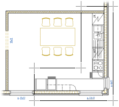
You can easily define a rectangular area by selecting two points: the start and end point of the diagonal of the rectangle.
- Select Confirm.
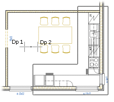
- Select the first direction point (Dp1).
- Lock the cursor, if necessary.
- Select the second direction point (Dp2).
- Type a label for the interior view in a text box.
- Type a name for the interior view in a text box. The View Tasks dialog box is opened.
- Select the interior view you just defined from the Views list.
- Select the check boxes Update views and Update models.
- Click the Open button.
- Type the scale for the interior view. The view is opened in a separate drawing window.
- Close the view by clicking the window’s Close button.

 Note
Note
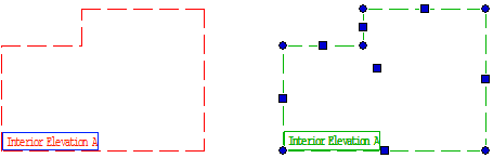
- The edge lines of the target area and the label of an interior view are displayed in the
floor plan drawing. You can edit the edge line by moving the grip points. You can add or
delete edge line points. Once you have edited the edge line of the area, update the view.
- The drawing properties of the edge line and label are defined in the system settings. The name of the line is VIEW_LIMITS, and the name of the label text is VIEW_LABEL.