
Add a Profile
Architectural, Framer
A profile can act as a beam; column; rafter, ceiling joist or floor joist; eaves trim, corner trim or wall finishing trim; or for another purpose. Add a profile as follows:
- Do either of the following:
- Select Modeling | Accessory Component |
 Profile.
 - Right-click to open the context-sensitive menu, and select Profile.
- Select Modeling | Accessory Component |
- Select the profile properties in the dialog box.
You can copy the profile properties from an existing profile by clicking the Pick button in the dialog box. Click the profile in the model or in the floor plan.
The status bar displays the cross section information and the purpose of the profile to be added.
You can open the properties to the dialog box again by selecting
 Properties from the auxiliary menu.
 -
If necessary, change the direction of the cross section with the functions in the auxiliary menu.
 Match Cross Section Direction to Plane
Normal
Match Cross Section Direction to Plane
Normal Match Cross Section Direction to Another
Profile
Match Cross Section Direction to Another
Profile Select Cross Section Direction
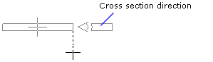
When you add a profile in the 2D drawing, the cursor shows the direction of the cross section.
- Select the locating point at the start of the profile in one of the following ways:
- Select one of the nine points on a rectangle drawn around the cross section as the
locating point from the auxiliary menu.

- Select the
 Select Locating Point function from the
auxiliary menu, and select any point on the cross section as the locating point. If
required, you can change the locating point to one of the nine quick-selection points,
and then activate the selected locating point again by selecting the
Select Locating Point function from the
auxiliary menu, and select any point on the cross section as the locating point. If
required, you can change the locating point to one of the nine quick-selection points,
and then activate the selected locating point again by selecting the  Free
Locating Point function.
Free
Locating Point function.
- Select one of the nine points on a rectangle drawn around the cross section as the
locating point from the auxiliary menu.
- Select the start point of the profile.
- If necessary, select the locating point for the end of the profile. The locating point can
be a different point at the start of the profile and at the end. Open the locating point
menu for the end of the profile by using the function
 Common/Separate Locating Point for Start And End Points.
 - Select the end point of the profile.

 Note
Note
- You can change the direction of the cross section also by using the cursor keys:
- Left - Counter-clockwise at intervals of 90°.
- Right - Clockwise at intervals of 90°.
The direction of rotation is determined by viewing the cross section from the end point of the profile towards its start point.
- When adding a profile, you can change its locating point, direction or properties at any time.
- You can form joints and add joint components between profiles by using the Connection Details function.