Truss Connectors
Form the joint between a truss and a wall or another support structure below it. When you move the truss, the joint components move with it.
- Select Modeling | Connection |
 Joint
Joint  Profiles
 Connection
Details. The browser is opened.
Connection
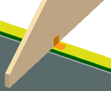
Details. The browser is opened. - Select the Trusses folder in the browser. Select the Angle bracket joint.
- Select the joint component and joint properties in a dialog box.
- Select the Custom or Standard library.
- To select the joint component, click the Select button. The button opens a list in accordance with the library selected, from which you can select the joint component.
- Select either of the following:
- One Side - The joint component is only added on one side of the truss.
- Both Sides - The joint component is added on both sides of the truss.
- Select the truss. Select several trusses with the Ctrl key pressed down.
- Select Confirm.
- Determine the position of the joint components. Make the following selections in the
dialog box:
- Select one of the following as the method of specification for the wall or the support.
- Wall - The joint component is added to intersection point of the truss and the center line of the wall selected.
- Line - The joint component is added to the intersection point of the truss and the line selected.
- Point - The joint component is added to the point selected.
- Support - The joint component is added at the truss support. The support can also be a support macro.
- Select one of the following as the positioning height of the joint components.
- Above - At the height of the top chord of the truss.
- Below - At the height of the bottom chord of the truss.
- Select one of the following as the method of specification for the wall or the support.
- Select a wall, line, point or support. The program will mark the positions of the joint
components with arrow symbols.
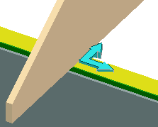
- If necessary, mirror or rotate the symbols before accepting the joints. Click the
FUNCTION button and select one of the following:
- Mirror. Select the symbols to be mirrored.
- Rotate. Select the symbols to be rotated.
- Mirror all. All symbols are mirrored automatically.
- Rotate all. All symbols are rotated automatically.
- Select Confirm.
- If necessary, delete the existing joint by selecting Delete in a
message box.
The geometry of the joint components is displayed both in the 3D model and the 2D drawing.