
Adding Macro Components to a Panel Drawing
Framer
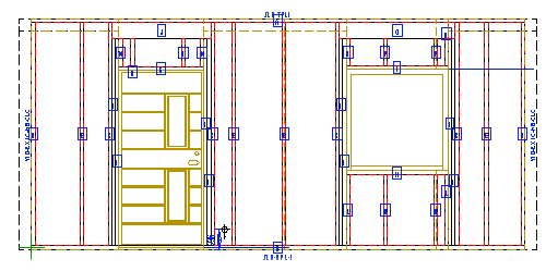
The geometry of macro components can be made visible in a wall panel drawing. Using this function requires that the wall panel settings be edited. Editing the settings is the system administrator’s task.
- Select System | Structural Libraries |
 Wall
Wall 
 Automatic
Execution.
Automatic
Execution. - Find the keyword ACCESSORIES. If the keyword is not found, you can add it to the database
as follows:
- Add a new row to the database or copy an existing row.
- Enter, for example, the following in the Description field:
Adding Macro Components to a Panel Drawing
- Select value 1 from the Exec list.
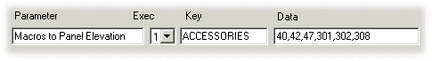
- Enter the following in the Keyword field:
ACCESSORIES
- In the Data field, enter the type numbers of the macro components
you wish to add to the wall panel drawing. Use a comma as the separator. For example:
- 301 - Window
- 302 - Exterior door
- 308 - Interior door
- Confirm by clicking OK.
 Note
Note
- If the macro components are not visible in the wall panel drawing, set all layers visible
with the
 All
Layers function on the tool strip.
All
Layers function on the tool strip. - You can deactivate this feature by selecting 0 in the Exec list.
- The program will save the changes made in a user-specific database. If the database is not found in the Custom folder, it is first copied from the System folder. Confirm the copying by clicking Yes in the message box.
- System tab is only available if you are a system administrator.