
Adding an Alignment Point
Option System
The elevation views are added on the elevation drawing sheet as reference drawings. You can define the location of different elevation views and other drawings, for example text drawings, on the elevation drawing sheet using alignment points. The alignment point is a macro that you can define a code for. The code can be used to align drawings on a drawing sheet.
First add an alignment point to the floor plan drawing, for example 1st Floor Walls drawing. Type a code for the alignment point, for example 1W (for 1walls). The program will automatically generate alignment points with the same code 1W to the elevation view drawings (elev-B.vxp, elev-F.vxp, elev-L.vxp and elev-R.vxp).
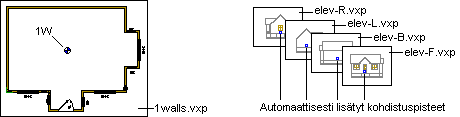
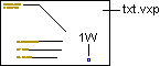
If you want to reference a text drawing to the elevation drawing sheet, you should add an alignment point with the same code 1W to the text drawing file.
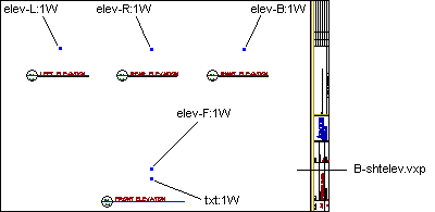
Finally, add alignment points to the elevation drawing sheet (file name B-shtelev.vxp, for example). The code of these alignment points should be of the following format:
file:1W
where "file" is the file name of the drawing to be added as a reference drawing, for example elev-F:1W or txt:1W.
 Use the file name without the
extension .vxp.
Use the file name without the
extension .vxp.
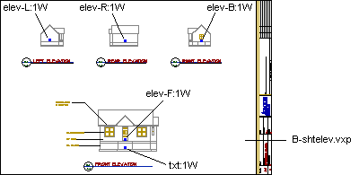
When the elevation drawing sheet is generated and the elevation views are referenced, the alignment points will match.
Add the alignment point as follows:
- Open the drawing. If you are adding the point to a file other than a drawing file of a
drawing-model pair of the project, open the drawing file with the function
 >
>  Open File.
 - Select Options |
 Optionalized Drawings
 Add Alignment
Point.
Add Alignment
Point. - Type a code for the alignment point.
- Select the location of the point. You can use the functions in the auxiliary menu when selecting the location.

 Note
Note
- Add the text drawing on the elevation drawing sheet with the function Add a Drawing on a Sheet. Save and close the drawing sheet. The alignment points of the text drawing and the drawing sheet will match when you update the drawing sheet with the function Update and Open a Drawing Sheet.
- The drawing files are stored in the following folders under the project folder:
- Elevation view drawing files elev-L.vxp, elev-R.vxp, etc. in the folder View_Dwgs.
- The elevation drawing sheet file #-shtelev.vxp in the folder View_Sheets.
- The text drawing files in the folder you have saved them into, for example View_Templates.
- You can edit the alignment point code as follows:
- Select the point in the basic mode of the program.
- Right-click to open the context-sensitive menu.
- Select Properties.
- Edit the code in a database view.
- You can create optionalized text note drawings for different elevation alternatives, see Optionalized Drawings.