
Cross Section Positioned Freely
Profile Structure Design
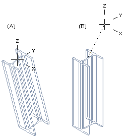
Sweep the profile cross section from the starting point selected in the working window in the specified sweep direction.
The selection of the cross section's starting point attaches the profile's insertion point to the selected point. You can then move the profile freely (A) until you select the sweep direction (B) or the sweep plane.
A profile part created this way is not a fixed part of the assembly.
 Vertex G4 Mechanical: Positioning freely placed profile parts using geometric constraints is an unwieldy and unstable method of modeling profile structures. We recommend a method whereby the profile part is modeled utilizing a skeleton formed from a guide curve. Its shape can be easily edited, and the profile part will change according to any changes in geometry.
Vertex G4 Plant: A freely added profile part remains in place, and it does not rotate in the model. Geometric constraints are not formed between the profiles. If you use the Alt key when adding a profile, constraints are formed.
- Select one of the following:
- On the
 tab, in the Add group, select
  Add Profile (G4).
 - On the
 tab, in the Steel Structures group, select Add Profile (G4 Plant).
- On the
- Select a profile cross section from the library.
 Browse - Archives
 - Select the table ID determining the profile size from the list.
- If necessary, attach item data to the profile part.
- Select a position (start point) for the cross section in the working window. Position the first profile part of the model in the origin by clicking the middle mouse button.
- Define one of the following as the profile direction:
- Select the context-sensitive menu function X axis direction or press the U key.
- Select the context-sensitive menu function Y axis direction or press the I key.
- Select the context-sensitive menu function Z axis direction or press the O key.
- Instead of defining a sweep direction, define one of the following as the sweep plane of the profile:
- Select the context-sensitive menu function Horizontal(XY) Plane or press Shift+U keys.
- Select the context-sensitive menu function Vertical(XZ) Plane or press Shift+I keys.
- Select the context-sensitive menu function Lateral(YZ) Plane Or press Shift+O keys.
- Enter a length for the profile from the keyboard or select an end point.
- Select Confirm.
- You can change the length of a profile added in this way by editing the 3D sketch of the profile.
- If you do not define the position of a profile part accurately when modeling it, you need to position it in the assembly using geometric constraints. If necessary, you can fix it in place.