
Cross Section on a Point
Profile Structure Design
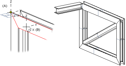
Sweep the profile cross section from the starting point selected in the model in the sweep direction or sweep plane.
For example, the point can be the end point of a line on an existing profile, the end point of a line on its cross section, a point on a guide curve, or another point on a line.
- Move the cross section selected from the profile library to a point, change the position of the cross section's insertion point, and select a point (A) as the starting point of the profile part.
- Select the direction of the normal of a planar face as the sweep direction (B).
- Enter the exact value for the profile length on the keyboard.
A profile part created this way is not a fixed part of the assembly.
- Select one of the following:
- On the
 tab, in the Add group, select
  Add Profile. (G4).
 - On the
 tab, in the Steel Structures group, select Add Profile (G4 Plant).
- On the
- Select a profile cross section from the library.
 Browse - Archives
 - Select the table ID determining the profile size from the list.
- If necessary, attach item data to the profile part.
- You can rotate the profile cross section or change the position of the insertion point by selection an auxiliary function.Change the Reference Point Rotate a Cross Section Change the Insertion Point
- Select a point in the model as the position of the cross section.
 You can select a point on a guide curve, other than the end point, by holding down Alt while clicking the left mouse button.
 - Define the face's normal direction as the profile direction, as follows:
- Click the following button:

- Select a planar face, the normal of which will determine the profile direction.
- Click the following button:
- Specify the profile length by entering a numerical value on the keyboard.
- Select Confirm.
Note:
- You can also select a point in the cross section of an existing profile part as the profile's starting point. Instead of length, you can select an end point, see Cross Section Between Two Points.
- It is easier to select a point from the model, when you enable snapping to Point.
- In profile part modeling, pressing the Esc key returns to the previous phase.
- If you cannot accurately determine the position of a profile part when it is modeled, it is positioned in the assembly using geometric constraints. If necessary, you can fix it in place.