
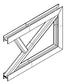
Cross Section on a Planar Face
Profile Structure Design
Sweeps the cross section of a profile from a planar face. The face's normal direction is the default sweep direction, but you can define another direction if necessary.
A profile part created this way is not a fixed part of the assembly.
- Select from the following options.
- On the
 tab, in the Add group, select
  Add Profile. (G4).
 - On the
 tab, in the Steel Structures group, select Add Profile. (G4 Plant).
- On the
- Select a profile cross section from the library.
 Browse - Archives
 - Select the table ID determining the profile size from the list.
- Select the table ID determining the profile size from the list.
- If necessary, attach item data to the profile part.
- If necessary, change the position of the insertion point of the profile cross section.
- If necessary, rotate the profile.
- Select a planar face in the model as the position of the cross section.
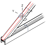
- Select another sweep direction if necessary. The face's normal direction is the default direction.Planar Face Normal as a Sweep Direction Line as a Sweep Direction
- Select the profile end point using one of the following methods:
- Specify the profile length by entering a numerical value on the keyboard.
- Click an end point or face.
- Select Confirm.
Note:
- If you cannot accurately determine the position of a profile part when it is modeled, it is positioned in the assembly using geometric constraints. If necessary, you can fix it in place.