
Cross Section Between Two Points
Profile Structure Design
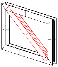
You can add a profile cross section between two selected points so that the cross section even has different insertion points at the starting and end points.
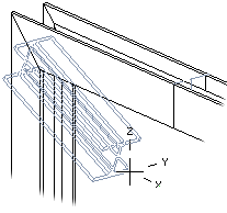
- To have the profile part set to the desired plane, you have to define the sweep plane.
- When sweeping a profile, you must always define the sweeping direction or sweep plane.
- A profile part created this way is a part fixed to the assembly.
- Select one of the following:
- On the
 tab, in the Add group, select
  Add Profile. (G4).
 - On the
 tab, in the Steel Structures group, select Add Profile. (G4 Plant).
- On the
- Select a profile cross section from the library.
 Browse - Archives
 - Select the table ID determining the profile size from the list.
- If necessary, attach item data to the profile part.
- Move the cursor near the starting point. Select a new position for the profile cross section's insertion point by clicking the button:

- Select a point as the position of the cross section.

- Define the sweep plane. Select the check box
 .
. - Select a planar face.

- Correct the position of the cross section by rotating it to the left.

- Select a new position for the profile cross section's insertion point in the upper corner point for the end point selection by clicking the button:

- Select the profile end point.

- Select Confirm.
Note:
- You can also use the context-sensitive function
 Add> Profile.