Exploded Drawing of an Assembly
After the exploded positions of the assembly parts have been defined, an exploded drawing is created. Place the assembly model in a favorable projection in the working window for an exploded view. You can add an assembly to the drawing in the projection in question.
In general terms, you can create an exploded drawing as follows:
- Create a new drawing or open an existing assembly drawing.
- Add a new projection of the assembly model to the drawing with the context-sensitive function
 Model View.
 - Select
 Assembly drawing in the New projection dialog box.
 - If necessary, change the other settings in the New projection dialog box.
- Select OK and position the projection.
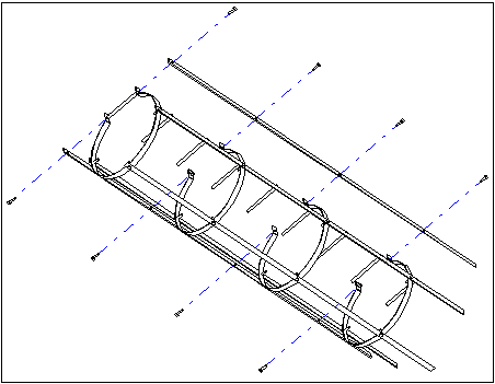
- Draw dashed lines between the parts with the
 Center Line function.