
Edit the Flashing Library
You can edit the flashing library in the Add Wall-to-Roof Flashing database view. The database view opens when you click the Select button in the Select Wall-to-Roof Flashing dialog box. You can edit the parameters of an existing flashing or create a new flashing. If you wish to create a new flashing, add a row to the database in one of the following ways:
- Copy an existing row as a basis. Select Edit > Copy Row.
- Add a new row. Select Edit > Add Row Before or Edit > Add Row After.
Edit Parameters
- Move to the desired row in the database using the cursor keys. If you added a new row to the database, enter a description text for the flashing in the Description field.
- Select a new profile from the profile library by clicking the Sel button. The Properties dialog box opens.
- Select RoofAcc from the Library list.
- Select the type and size of the flashing from the Code list. You
can select either the basic type (A) or the beveled type (B) from the list.
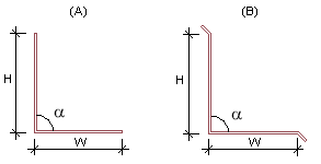
W = width
H = height
a = angle
- If you cannot find a flashing with the desired dimensions from the library, you can add a
new flashing by clicking the Edit button. The Parametric Library
database view opens. Make the following selections in the database view:
- Select either basic or beveled from the Type list.
- Enter the flashing width (W) in the Width field.
- Enter the flashing height (H) in the Height field.
- Enter the flashing angle (a) in the Angle field. Enter, for example, 90 as the default value in the field. The final angle is determined by the roof slope angle.
Confirm by clicking OK.
- Click OK to close the Properties dialog box. You will return to the Add Roof-to-Wall Flashing database view.
- Edit the contents of the Type field, deleting the angle value at
the end, so that the final angle is determined by the roof slope angle.
beveled 300x400 90
Change to: beveled 300x400
- Select the roof level at which the flashing is placed. Select one of the following from
the Flashing Level on Roof list:
- SIDING.TOP - Roof top surface.
- FRAME.TOP - Roof frame top surface.
- FRAME.BELOW - Roof frame bottom surface.
Enter the distance of the flashing from the selected roof level in the Flashing Height from Level field.
- Select the wall layer on which the flashing is placed. Select one of the following from
the Flashing Level in Wall list:
- SIDING - The exterior surface of the siding.
- SHEATHING - The exterior surface of the sheathing.
- EXTERIOR - The exterior surface of the frame.
Enter the distance of the flashing from the selected wall level in the Flashing Distance from Level field.
- Select the roof level from which the distance to the edge of the opening in the siding is
calculated. Select one of the following from the Opening Level from
Roof list:
- SIDING.TOP - Roof top surface.
- FRAME.TOP - Roof frame top surface.
- FRAME.BELOW - Roof frame bottom surface.
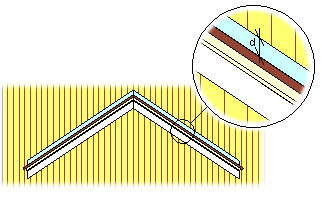
Enter the distance of the edge of the opening in the siding (d) from the selected roof level in the Opening Height from Level field.
- Save the database by clicking OK.