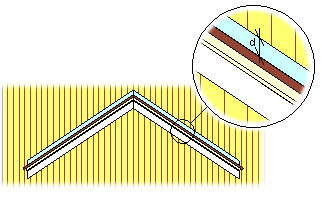
Selecting a Flashing
Select the flashing parameters in a dialog box.
Dialog Box Options
- Description
- Select a flashing from the library by clicking the Select button. The Add Wall-to-Roof Flashing database view opens. Move the cursor on the desired row and click the OK button to accept the selection. The description and other pre-defined parameters of the flashing are entered into the fields in the dialog box.
 Edit the Flashing Library
- Type, Profile Library
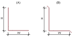
- The flashing's type, section diameters (width x height) and profile library name are displayed in the text fields. The basic version of the software features two different types: basic type (A) and beveled type (B).
- Roof Layer
- Select the roof level at which the flashing is placed. Select one of the following:
- Wall Layer
- Select the wall layer on which the flashing is placed. Select one of the following:
- Wall Siding Hole Top Edge
- Select the checkbox when you want to add an opening to the exterior siding at the flashing's location . Select the roof level from which the distance to the edge of the opening in the siding is calculated. Select one of the following: