
Corner Connection, L Connection
When you add a wall chain, the corner connections between walls are automatically created. A connection is also formed when you select an end point of an existing wall as the start or end point. If a connection is not formed, or it is broken up, you can create a connection.
- Corner joint in the connecting point of two diverging walls.
- Butt joint between parallel walls in a parametric building model, see Wall Butt Connection.
You can select the function in the following ways:
- From the ribbon
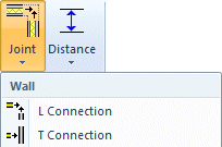
- Select Modeling | Connection |
 Joint
Joint  Wall L Connection.
 - Select the end of the first wall that is closest to the joint.
- Select the end of the second wall that is closest to the joint.
- Select Modeling | Connection |
- From the wall grip point menu
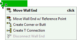
- Select a wall.
- Move the cursor near the grip point of the wall end. The grip point turns green.
- Right-click to open the context-sensitive menu of the grip point.
- Select
 Create Corner or Butt.
 - Click the end of the other wall.
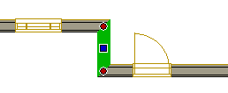
The grip point at the end of a wall is red when the end is connected to another wall. The grip point is blue when there is no connection.
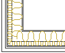
- In the Vertex BD Architectural and Pro products, this function includes an advanced function DET OFF/ DET ON:

With the DET OFF advanced function, the program creates a basic corner joint so that the lines depicting different layers in the 2D drawing are trimmed to the line between the intersection of the inner faces and the intersection of the outer faces of the walls, for example:
When you select the advanced function DET ON, you can select the joint from a joint library or, if a ready-made joint for the selected wall types does not exist, you can model the joint and add it into the joint library.
- You can remove the connection between walls by using the function Delete a Wall End Connection.
