
Wall Parameters
Wall parameters are available for selection in the Wall dialog box when you have made a wall thumbnail image active by clicking, and no layer is selected in the Layers list or the preview image. If necessary, deselect a layer by clicking an empty space in the Layers list.
By default, only some parameters are displayed in the dialog box. You can display more parameters as follows:
- Open the context-sensitive menu in the parameter list.
- Select Show All Parameters.
You can select the following parameters for a wall:
-
Color fill for whole wall - When this check box is ticked, the wall's color fill will be displayed in the floor plan. All layers will then have the same color fill.

When this check box is empty, the color fill for the whole wall is disabled. However, you can define individual color fill parameters for each layer. These color fills will be displayed in the floor plan when the color fill for the whole wall is disabled.

Select the color from the list or palette.
-
Select one of the pre-defined color options.

-
 Palette - Select a color from the palette. The colors of the palette are defined in the program's setup file, user/pmap.
Select the order of the colors:
- Hue Order
- Numeric order
Select a new color by clicking from the palette. The old color and the new color selected are displayed in the dialog box. The RGB value of the color is displayed on the right side of the image and its number below the image.
Preview displays the color over which the cursor is on the palette.
Click the Use Default Color button to use the default color of the element, defined in the settings.
- ACI Palette - Select a color from the AutoCAD Color Index palette.
 RGB-palette - Select a color from the palette.
Define a new color by clicking Define Custom Colors. Fill in the color properties, and select Add to Custom Colors.
The color fills will be displayed in the plan when the Show Color Fills setting is enabled.
- Select
 >
>  Preferences >
  Drawings, Models.
 - Select the View tab.
- Select Drawing:
 Show Color Fills.
-
-
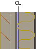
Centerline - When this checkbox is ticked, the centerline of the wall (halfway between the exterior surface of the exterior siding and the interior surface of the interior siding) is drawn on the floor plan. Select a pre-made property set for the line from the list, or define the Line type, Layer, Pen, Scale, and Color properties individually.
-
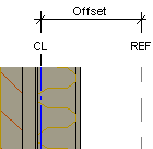
Reference line - When this check box is ticked, the wall has its own reference line. When adding a wall, you can either select one of the quick selections (exterior surface, centerline, interior surface) or the wall's own reference line using a separate function, see Placement: According to Wall Reference Line. Select a pre-made property set for the line from the list, or define the Line type, Layer, Pen, Scale, and Color properties individually.
Define the line placement by selecting a value for the Offset property. This property determines the line's distance from the wall's centerline. With positive values, the line is placed outwards from the centerline, with negative values, it is placed inwards.
-
Extra line - You can define one or several extra lines for a wall. Extra line is not available for selection in the list as a default, but you can add one for the wall as follows:
- Open the context-sensitive menu in the list.
- Select Add Line.
Enable extra line by ticking the checkbox next to it. Select a pre-made property set for the line from the list, or define the Line type, Layer, Pen, Scale, and Color properties individually. Define the line placement by selecting a value for the Offset property. This property determines the line's distance from the wall's centerline. With positive values, the line is placed outwards from the centerline, with negative values, it is placed inwards.
You can delete an extra line as follows:
- Select the extra line from the list.
- Open the context-sensitive menu.
- Select Delete Line.
- Use project default heights - When this checkbox is ticked, the height positions of the top and bottom edges of the siding and framing layers are read from the project parameters. Other layers retain their height in relation to the framing layer.
- Bearing - When this checkbox is ticked, the layer is load-bearing. This information is required in wall panel design. The selection is also displayed in the common properties of building components, see Common Properties to an IFC File. You can edit the selection by editing either the wall properties or the common properties.
- U-value - The U-value is used in energy calculation.
 Indicative U values have been determined for the building components in the structure libraries included in the basic software delivery. If you edit the number, thickness or materials of layers, the U value is not updated automatically. If necessary, recalculate the U value and update the new value to the properties. The value is also displayed in the common properties of building components, see Common Properties to an IFC File. You can edit the value by editing either the wall properties or the common properties.
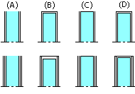
 - Free end cap - The default value for a free end cap of an interior wall is defined in the project parameters with the parameter WALL_END_CAP. You can change the value for a specific wall in the wall properties. Enter the thickness of the cap as a numerical value in the field, or type one of the following in the field:
- NO : Wall is not capped (A).
- YES : Wall is capped (B). If the wall has double sheathing, the thickness of end cap is the total thickness of sheets.
- SINGLE : A line is added at the end of the wall (C).
- DOUBLE : Same as YES. A feature to be custom-fitted.
- SHEET: Wall is capped (D). If the wall has double sheathing, the thickness of end cap is the thickness of outer sheet. If the interior and exterior sheathing are in different thicknesses, the thicker sheet will be used.
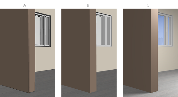
Note: Use uppercase letters.The above parameter adjusts the representation of the wall in the floor plan. In the model, the actual sheet is not added, but the color of the free end surface is set to the same color as the interior surface of the wall.- A - The graphics setting Show edges is enabled.
- B - The graphics setting Show edges is disabled.
- C - A rendered model.
You can disable this feature by setting the following keyword in the user/SETUP file:
set.free_end.color= 0
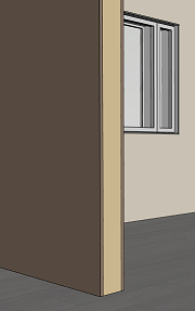
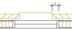
- Siding overlap on openings - Type the length of the siding overlap (L) measured from the opening edge in the text field.
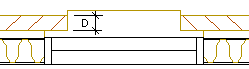
- Siding overlap depth - Type the depth of the siding overlap (D) measured from the exterior surface of the siding in the text field.
-
Opening reference line - By default, the opening frame is positioned in the middle of the wall frame. For openings, you can select a reference line differing from the default line by defining the wall line to which the interior surface of the window frame is positioned. Enter the value in the format [macro type]:[name of wall line]. The window macro type is 301 and the door 302. Positioning the interior surface of the window frame to the interior surface of the wall, for example:
301:INTERIOR FINISH
You can set a different reference line for different types of openings. Separate the definitions from each other with a vertical bar:
[macro type]:[name of wall line]|[macro type]:[name of wall line]
For example:
301:INTERIOR FINISH|302:EXTERIOR
-
Opening offset - Type the distance of the opening from the reference line in the text field. A positive value moves the opening outwards, negative inwards. When the field is empty or the value is 0, the opening is positioned on the reference line. Enter the value in the format [macro type]:[offset]. The window macro type is 301 and the door 302.
You can set different reference lines and also an offset from the reference line for different types of openings. Separate the definitions from each other with a vertical bar:
[macro type:offset]|[macro type:offset]
For example:
301:70|302:0
- Dead load of structure [kN/m^2] - This parameter is only visible if you use the Vertex BD add-on option for structural calculation.