
Log Wall Corner Joints
When you add log walls, a default corner joint is created between the walls. If necessary, you can delete the default corner joint and add a corner joint from the joint library. The type of a corner joint can change several times in one corner. You can define the height of the joint by clicking the logs in the model. You can stretch the logs outside the joint by moving the end of a log from grip point in the model.
- Select Modeling | Connection |
 Joint > Profiles
  Connection Details. The browser is opened.
 - Select the Log Connections folder in the browser.
- Select one of the following joints:
- 0001 T-connection
- Select the target wall.
- Select the ending wall.
- Select the joint properties in the Passing Joint dialog box.
- 0002 Corner, symmetric
- Select the first wall.
- Select the other wall.
- Select the joint properties in the Passing Joint dialog box.
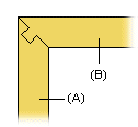
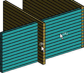
- 0005 Mitered dovetail corner FF
- Select the first wall (A).
- Select the other wall (B).Note: If necessary, re-add the joint and change the pointing order of the walls.
- Select the joint properties in the Dovetail Joint dialog box.
- 0006 Dovetail T-connection
- Select the target wall.
- Select the ending wall.
- Select the joint properties in the Dovetail Joint dialog box.
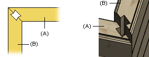
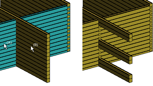
- 0007 Mitered dovetail corner
- Select the wall with the mortise (A).
- Select the wall with the tenon (B).
- Select the joint properties in the Dovetail Joint dialog box.
- 0008 Dovetail corner
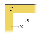
- Select the wall with the mortise (A).
- Select the wall with the tenon (B).
- Select the joint properties in the Dovetail Joint dialog box.
- 0009 City-notch corner
- Select the first wall (A).
- Select the other wall (B).
- Select the joint properties in the City-notch dialog box.
- 0010 City-notch cross
Once you have created the joint, you can stretch or shorten the logs in the crossing wall by moving the end of a log from the grip point.
- Select the log wall (A).
- Select the crossing wall (B).
- Select the joint properties in the City-notch Cross dialog box.
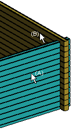
- 0011 City-notch T-connection
- Select the target log wall (A).
- Select the ending log wall (B).
- Select the joint properties in the City-notch T-connection dialog box.
- 0001 T-connection
- You will be prompted: "Remove present joints?" Select one of the following:
- When creating the first joint for the corner, select Delete to remove the default corner joint.
- If you are adding a joint without lower and upper limits for the height, select Delete to have the entire corner use the same kind of joint.
- If you have already added a joint for which you have defined lower and upper height limits, and you are adding another kind of joint at a different height, select Keep to retain the old joint. If the joints interfere with each other, the program will undo joints until the interference disappears.
Note:
- The program adds a symbol in the floor plan drawing on the layer 89. You can display the symbol by selecting the layer to be visible. You can later edit the joint properties by double-clicking the symbol in the floor plan drawing. For example:
-
 - Dovetail Joint
 -
 - Passing joint
-
- The joint types have their own machinings which will be included in the log work drawings and the machining list.
- You can later edit the joint properties by double-clicking the symbol in the floor plan drawing.