Cross Section
Define the sketch as a cross-section, and use the sketch later to form a volume. As an example, creating a sweep, loft, extrusion or revolve. Draw a new sketch, accept it and define it as a cross section.
- Open the part model in the working window.
 Browse - Archives
 - Select the context-sensitive function
 New Sketch.
 - Draw a sketch whose lines form a closed polyline.
- Select Confirm.
- Select

 Cross Section as the operation.
 - Click OK.
Note:
- Edit the cross-section sketch, when you select the cross section and the context-sensitive function Edit sketch.
- Edit the cross-section sketch by selecting the sketch from the feature tree, and by the context-sensitive function Edit.
- If the cross section is formed of a very complex and detailed outline, it can prevent the feature, for example a loft or a spiral, from being modeled because of computational reasons. Usually this can be resolved by making the cross section outline simpler.
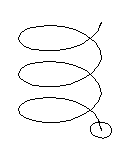
Cross section on a guide curve
If you wish to position a cross section on a guide curve, you will need to define the guide curve before creating the cross section. Sketch the cross-section to the guide curve, or paste the copied cross-section to the sketch guide curve. The program will add a sketching coordinate system to the guide curve. The cross section lines will from a closed polyline.
Define a cross section to a guide curve as follows:
- First, select the guide curve.

- Select a line of a guide curve.
- Do either of the following:
- Select the context-sensitive function New Sketch.
- Add a copied cross-section sketch to the guide curve using the context-sensitive function Paste Sketch.
- Select the context-sensitive function
- Define the origin of the sketching face on the line.
- Draw the sketch of the cross-section, or edit the sketch you pasted.
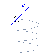
- Select
 OK.
OK. - Select as the sketch operation Cross Section, and select OK.