
Round Feature Data
Define the rounding feature properties: the rounding radius and the variable value corresponding to the position of the radius on the line. Specify the feature data in the dialog box.
- Radius
- Formula
- Param
Dialog Box Options
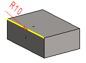
- Radius
- Defines the radius value for rounding a line. The smallest allowed radius value is 0. The angle value will be displayed in the model. The radius will be highlighted in red when its value can be edited.
 By clicking the OK button in the dialog box, you can model the feature using the new values. You can edit more than one radius value sequentially by selecting one radius at a time. After editing one value, select the next one, etc. When you have finished making the changes, click OK button.
- Formula
- Defines the radius as a variable.
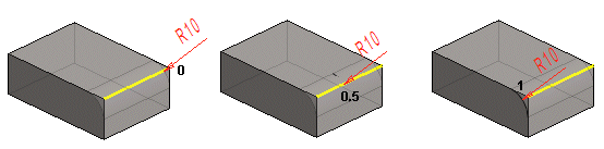
- Param
- Defines the position of the radius on the line. As a default, the rounding radius will be located at the center of the line, so the variable value will be 0.5. You can accept this default value when you wish to use the same rounding radius for the entire line.
- Adding a Line
- Add a line to a rounding by holding down Ctrl and selecting the line. Add a line when adding or editing rounding.
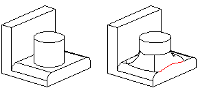
- Capped edge line (default)
- If you are creating a rounding between a face and a face, or a face and a line, the edges of other faces touching the rounding will be capped.
- Roll edges
- If you are creating a rounding between a face and a face, or a face and a line, the edges of other faces touching the rounding will be rolled when you select one or more face edges, by holding down Ctrl while clicking with the left mouse button. In the dialog box, rolled edges are indicated with the Roll text.
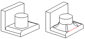
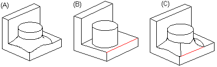
- When the rounding touches a cylinder face, the rounding will be set on top of the face.
- True Preview
- Select either of the following:
 - This will show you how the model would look with the values of the rounding when you select Apply.
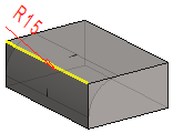
 - You can view the line you selected to round. The entered radius value is updated in the preview image when you select Apply. Geometry will note be updated in the preview image.
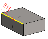
- Apply
- Preview by clicking the Apply button in the dialog box. This will show you how the model would look if you confirmed the feature data by clicking OK. If necessary, you can still edit the feature data.
- Unattached
- The lines/points of a failed feature, no longer existing in the geometry of the part, are indicated with an asterisk (*) and Line0 marking. Select the element (*) to be attached from the list and then a new line/point while holding down Ctrl.
- Click the OK button only when you want the feature to be modeled using the values entered.