
Feature Pattern Data
This function can be used to define a linear or polar feature pattern. Define the feature pattern properties in the dialog box.
Dialog Box Options
- Linear
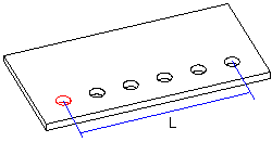
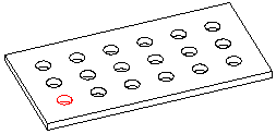
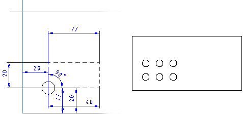
- Defines the feature pattern as linear. Click the Linear button. You can define a linear feature pattern on a part for example in either one direction or in both the longitudinal and latitudinal direction. For a linear feature pattern, define the number of features, either the length (width) or the distance and the feature pattern angle among other things with which the features will be set.
 Symmetric
- Select the check box Symmetric if you want to create a symmetrical feature pattern. Locate the feature to the symmetry center and then create a pattern from the feature.

- Polar
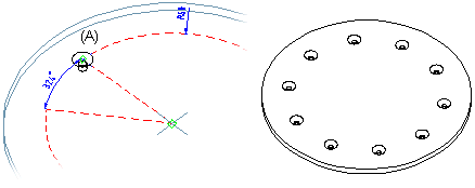
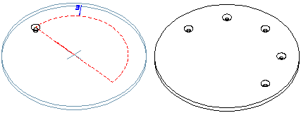
- Defines the feature pattern as polar. Click the Polar button. For a polar feature pattern, define the number of features, the angle between features and the radius among other things with which the features will be set.
- No rotation
- An asymmetric feature will be rotated in a polar feature pattern. You can prevent rotation of a feature by selecting the No rotation check box.
- Number
- Defines the number of features to be added to the part. The parent feature, based on which the feature pattern is created, is counted as one of the features in the feature pattern.
- Formula
- Defines the feature pattern property, for example amount, length, width variable.
- Length
- Defines the length value (L) in the longitudinal direction at which the features will be set at equal distances. The direction of the positive X axis determines the longitudinal direction on the part (default). To check the directions of the axes, press the K button in the sketching mode to make the cursor a coordinate cursor. You can make the check after confirming the feature pattern properties. If necessary, you can rotate the feature pattern.

- Width
- Defines the width value (W) in the latitudinal direction at which the features will be set at equal distances. The direction of the positive Y axis determines the latitudinal direction on the part (default).

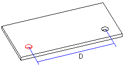
- Scale
- Defines the distance (D) left between the features in either the longitudinal or latitudinal direction. Define a linear pattern to length’s direction: 2 pieces of components, the length is 120.
- Radius
- Defines the radius value for a polar feature pattern. If no radius value is entered, the program will use the default radius value (R=100).
- Angle: Linear Feature Pattern
- Defines the angle of a linear feature pattern. The angle of a symmetric feature pattern is 90 degrees, but you can also define another value.


- Angle: Polar Feature Pattern
- Defines the angles at which the features will be set at equal distances. The features will be set clockwise in relation to the parent feature.
- Deleted
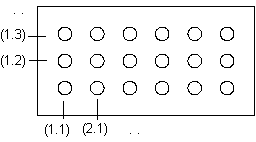
- Defines the features to be deleted from a feature pattern. The position of the features is given as the XY coordinates, entered in parentheses. A period (.) is used to separate the X and Y coordinates. In the Deleted field, you can enter several features to be deleted one after another, for example, (1.1)(1.3). The parent feature is (1.1). You can define the features to be deleted when creating the feature pattern or when editing it.
- Pattern Location
- Defines the insertion plane of a feature pattern. Select one of the following in the list: