Polar Feature Pattern
Copy the feature by the equally spaced polar.
- On the
 tab, in the Tools group, click
  Group pattern.
 - Select the surface from the feature, from which you create the pattern.
- Define the feature pattern properties in the dialog box.
 Feature Pattern Data
 - Click OK.
- Select the position, and select the context-sensitive OK.
From the context-sensitive menu - Polar feature pattern.
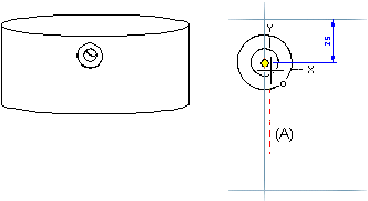
You can create a polar feature pattern from a parent feature. A parent feature can consist of more than one feature. After selecting the parent feature, define the feature pattern properties in the dialog box. Once you have defined the properties, you can position the feature pattern sketch.
Position the sketch on an element (point, line) of the parent feature using the origin of the sketch as the insertion point. The angle and radius are illustrated in the feature pattern sketch. If you do not enter a radius value, the program will use the default radius (R=100). You can edit a polar feature pattern in the same way as a linear feature pattern.
Add the polar feature pattern.
- Do either of the following:
- Select one or mode Boss or Cutout operation from the part's feature tree.
- Select on or more face from the part. Select more than one feature by by holding down Ctrl while clicking with the left mouse button.
- Select the context-sensitive function Feature Pattern.
- Click the Polar button in the dialog box.
- Define the feature pattern properties in the dialog box. Feature Pattern Data
- Select OK.
- Select an auxiliary function to rotate a pattern, for example.
- Position the feature pattern from its origin to the center point of a pattern.
- Define geometric constraints for the sketch if necessary.
- Select Confirm, after the the feature pattern is positioned to the part.
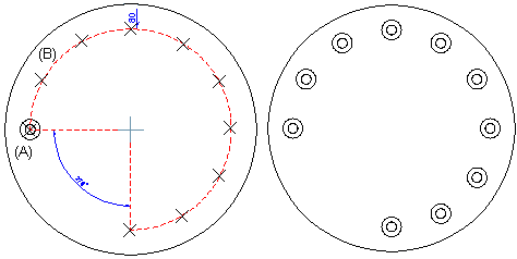
Create a polar feature pattern using the parent feature (A). Define the number of features as ten and the angle as 270 degrees. Position the origin (B) of the feature pattern sketch at the center point of the parent feature. The positions of the features are illustrated with crosses when the feature pattern is being positioned. Accept the sketch.
Polar feature pattern on a cylinder face
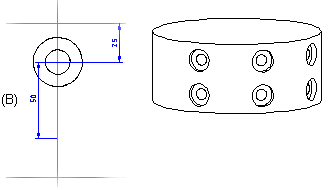
You can also add a polar feature pattern to a cylinder face. You can create the feature pattern using a parent feature added to the cylinder face. After selecting the feature, define the circle properties in the feature pattern properties. If you wish to add the features to more than one row, also define the longitudinal direction properties.
- Create a polar feature pattern on a cylinder face using a parent feature. Enter the following properties for the feature pattern: twelve features, angle 360 degrees.
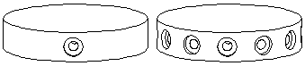
- Create a feature pattern in two rows. Enter the following properties for the feature pattern: three features, angle 90 degrees. Enter the following longitudinal properties: two components, delta 50. two features, delta 50. In the sketching mode, the first feature pattern sketch depicts the length that defines the distance between the two rows. As we wish to position the second row below the first one, we need to rotate the sketch 180 degrees and then position it at the center point of the parent feature, using the origin of the sketch as the insertion point.
The program will automatically add a Distance constraint to the sketch. Confirm the data.