
Linear Feature Pattern
Create the linear feature pattern from the parent feature. The parent feature can be a feature based on a sketch, a sweep, a loft, a library feature, or an editing feature such as a rounding or a bevel. A parent feature can contain more than one feature.
- On the
 tab, in the Tools group, click
  Group pattern.
 - Select the surface from the feature, which the pattern is created.
- Define the feature pattern properties in the dialog box.
 Feature Pattern Data
 - Click OK.
As the context-sensitive - Linear feature pattern.
Create the linear feature pattern from the parent feature. The parent feature can be a feature based on a sketch, a sweep, a loft, a library feature, or an editing feature such as a rounding or a bevel. A parent feature can contain more than one feature.
After selecting the parent feature, define the feature pattern properties in the dialog box. You can define a linear feature pattern in the longitudinal or latitudinal direction or in both directions.
After defining the data, the feature pattern sketch will be displayed in the sketching mode, illustrating the dimensions and direction of the feature pattern.
Position the sketch on an element (point, line) of the parent feature using the origin of the sketch as the insertion point. If necessary, you can rotate the sketch before positioning the feature pattern. You can define the position of the sketch on the part using geometric constraints. You can also define a geometric constraint for a line on the feature pattern sketch.
The features in the feature pattern are copies of the parent feature, and are associated with it. When you edit the parent feature, the changes will be reflected in all of the features in the feature pattern.
Create a linear feature pattern as follows:
- Select the parent feature from a part as follows:
- Select one or mode Boss or Cutout operation from the part's feature tree.
- Select on or more face from the part. Select more than one feature by by holding down Ctrl while clicking with the left mouse button.
- If you want to create a feature pattern from a rounding or a bevel, you must also include the feature to whose geometry the rounding/bevel has been added.
- Select the context-sensitive function Feature Pattern.
- Click the Linear button in the dialog box.
- Do either of the following:
- Define the feature pattern to one direction: length or width direction.
- Define the feature pattern in the longitudinal and latitudinal direction.
- Click OK.
- Select an auxiliary function to rotate a pattern, for example.
- Move the feature pattern from its origin to the parent feature's entity.
- Define geometric constraints for the sketch if necessary.
- Select Confirm, after the the feature pattern is positioned to the part.
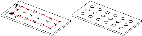
Create a linear feature pattern using the parent feature (A). Define the number of features as six in the longitudinal direction and three in the latitudinal direction, at equal distances. Position the origin (B) of the feature pattern sketch at the center point of the parent feature. The positions of the features are illustrated with crosses when the feature pattern is being positioned. Accept the sketch.
- A feature pattern cannot be created from just a rounding or a bevel.
- When more than one feature has been selected for the parent feature, the feature pattern sketch is added to the sketch of the oldest feature in the modeling history of the part. You can edit the feature pattern by selecting the oldest feature Feature Pattern symbol from the feature tree, and the context-sensitive function Edit Pattern.
- When positioning a feature pattern sketch on a line or point of the parent feature using the origin of the sketch as the insertion point, the program will automatically add the Coincident constraint. When you position a line at a center point, the Center point constraint will also be set.
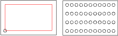
- The position of the parent feature is relevant when adding a feature pattern. The feature pattern will be set in the direction of the positive axes (default). Compare the examples below:
- Add the library feature (A) to the part and create a feature pattern. When you position the feature pattern sketch, some of the features in the feature pattern will be left outside of the part. Rotating the feature pattern does not help.
- Add the library feature (B) to the part and create a feature pattern. The feature pattern will be set as desired.

- Edit the parent feature by double-clicking the feature symbol, and redefining the feature properties. You can select a new size for a library feature from the dimension table. The new feature will also be updated in the feature pattern.
- You can use the dimension table to edit a feature pattern when variables have been defined for the geometric properties of the feature pattern.
Example: Linear Feature Pattern
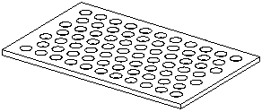
Create a hole pattern using two feature patterns.
- Add the first library feature, use it to create a feature pattern, and position the feature pattern sketch at the center point of the parent feature. Confirm the sketch.
- Add the second library feature, use it to create a feature pattern, and position the feature pattern sketch at the center point of the parent feature. Confirm the sketch.
