
Weld Data 3D
In this dialog box, you can define the data for a weld being added, edit data or delete a weld. When you are adding a weld, the dialog box is also displayed when you are clicking elements in the model for the new weld. Once you have clicked the elements for the weld in the model, the weld is displayed on the list in the dialog box.
- You can view the welds of a model by selecting them from the list. The selected weld is highlighted in the model.
- You can edit the weld data by selecting the weld from the list, edit the data and update the modifications in the model by selecting the Apply button.
- You can add a weld by clicking an empty line in the weld list, define the weld data and click elements connected to the weld.
- You can delete individual welds in the dialog box. Select the weld to be deleted from the list and click the Remove button.
- When you accept the welds added to the model by clicking the OK button in the dialog box, the
 part appears in the assembly tree.
Dialog Box Options
- Type
- Defines the weld type as Angle Weld or Butt Weld. The selected weld type determines what choices are available in the dialog box.
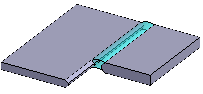
- Click Start/End
- You can click the start and end points for the weld on the sweep line when this checkbox is selected. The weld is added on the line or polyline between the start and end points.
 Start and End of an Angle Weld Start and End of a Butt Weld
- Description
- Enter a description for the weld before clicking its elements. The description text makes it easier to identify the weld on the list.
- Offset 1, Offset 2
- Defines the offset values for the weld when the Click Start/End checkbox is selected.
 An angle weld's direction is determined by the right-hand rule. The thumb points in the direction of the base plane normal, and the direction of the fingers in the fist determine the direction of the weld..
- A dimension, Z dimension
- Defines the weld to be added according to the A dimension or the Z dimension.
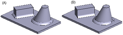
- Closed
- Defines an angle weld around the part (A), when this checkbox is selected. If the checkbox is empty, the angle weld will be added only on the selected sweep line (B).
- Shape 1, Shape 2
- Defines the weld profile: Convex, Concave, or Flat. Select a suitable profile. You can define a single shape for an angle weld.
- Cross Sections
- Determines the number of cross sections used to form the weld. The shape of the cross section is determined by the profile selected in the Shape field.
- OK
- Confirm the welds added to the assembly and stop adding welds.
- Delete
- If you wish to delete a weld in an assembly, click the weld to be deleted on the list. The selected weld is highlighted in the model. Delete the weld by clicking the Delete.
- Apply
- If you want to edit the weld data, select a weld from the list, edit the data and click the Apply button. The changes will be refreshed in the weld part.
- Undo
- You can cancel any changes made to welds by clicking this button.