
Add a Weld Feature
Profile Structure Design
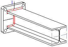
Model a weld feature in an assembly. A weld feature is an assembly feature.
- When you add a weld feature to an assembly, it will be displayed as a part model in the assembly tree.
- If you add a local subassembly to the assembly, you can add weld features in the subassembly. It's easy to hide welds in the model and restore them back to model.
 Local Subassembly
A weld feature is a fixed part of an assembly and is associated with the geometry to which it is attached.
Model a weld feature in an assembly as follows.
- Open the Browser. Browser - Archives
- Select a weld cross section from the weld library. Select the browser folder Libraries, select Profiles / Standard / Welds.
- Select a weld in the search result and select the context-sensitive Add.
- Edit the data in the dimension table, and select OK.
- Sweep the cross section of the weld along a line. Move the cross section over the line onto which you want to position the weld.
- If necessary, rotate the weld cross section.
- If necessary, change the position of the cross section's insertion point.
- Do either of the following:
- Select a line as the position of the cross section. Note that the cross section will be positioned on the point you click on the line.
- You can select a tangential polyline by first clicking the following button:
 and select the line.
- Edit the data in a dialog box, and select OK.
- Select Confirm.
Note:
- Weld features can only be modeled in an assembly. Weld feature modeling uses the same functions as the modeling of the other assembly feature, the profile part. In practice, weld features are created as Profile Sweep features.
- It is easier to select a line in a model, if you enable +... from the menu bar search to Line, or on the toolbar
 .
. - You can also add welds as follows: