Example - SmartSnap Component (Part)
Library
Make a cover that can be positioned in an assembly from its four corner points.
- Open, or create an assembly model that contains the geometry required to model the component.
- Create a new part (jig) in the assembly to help model the cover. You need the jig part for defining the cover's fixing points.
- Select the function New Part, and name the part.
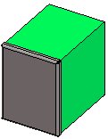
- Model a polyhedron.

- Create a new part in the assembly for modeling the cover.
- Select the New... function. Select
 Local in the new part data.
 - Name the part.
The jig part is displayed in the assembly as reference geometry.
- Select the New... function. Select
- Select the
 New Sketch> 3D Sketch function.
- Draw two lines in the sketch with the Lines> 2 Points function. Click the endpoints of the jig part's lines as the start and end points for the lines.
 Note that the order in which you click the points determines the order in which the fixing points will be prompted when the part (component) is being positioned in the assembly.
These two lines will determine the positioning of the part in the assembly as well as the geometric shape of the part.
- Once the lines have been drawn, four blue Coincident constraints are displayed in the feature tree (see figure above). They are coincidences to the part modeled first (jig).
You can rename the constraints in the feature tree by selecting a constraint and then selecting the Rename function.
For example:
- Left bottom corner point
- Right bottom corner point
- Right top corner point
- Left top corner point
- Select
 OK.
OK.
- Draw two lines in the sketch with the Lines> 2 Points function. Click the endpoints of the jig part's lines as the start and end points for the lines.
- Hide the jig part from the geometry.
- Move the cursor over the jig part in the assembly tree and press the H key.
- Add a sketching plane.
- Select a line and a point on the 3D guide curve.

- Select the function New Sketch.
- Select a line and a point on the 3D guide curve.
- Copy the lines of the 3D sketch to the sketching plane.
- Select both lines of the 3D sketch.

- Select the Copy to Sketch Plane function.
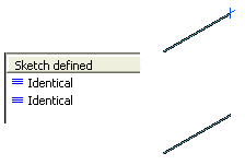
Once the lines have been copied, two Identical constraints are displayed in the feature tree.
- Select both lines of the 3D sketch.
- Make the polyline continuous.

- Select OK.
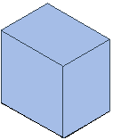
- Create a part with the Extruded Boss function.
- Select the cover for editing.
- Change the part type into Sheet-metal Part.
- Add bevels and other necessary details.
- Finally, save the part in the component library.
- Select the Save To Library> As Component function.
- Save your own components in the Shared folder. If necessary, create a new folder in the Shared folder. Name the component.
- Exit the modeling mode.
Try out adding the component in its place
- Try out adding your own SmartSnap component to one end of the jig part.
- Select the function
 Add> Component.
 - Select a component.
- The component is opened in a separate model window.
- Select the function
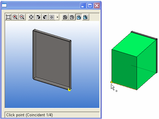
- Vertex will prompt you to click the fixing points for the 3D sketch. The part is positioned based on the matching points clicked.
- The constraint for which you have to click a matching point in the assembly is displayed on the prompt line of the component's model window.
- You can also see the number of constraints for which you need to click a matching point. For example, Coincident 1/4 means that you are clicking the matching point for the first constraint. There are a total of four matching points you need to click.
- The point is also highlighted in the component's model window. If necessary, you can rotate the component in the window in order to see the point in the model window.