
Example - SmartSnap Component (Assembly)
Library
Modeling an assembly component.
Phase 1
- Open or create an assembly that contains the geometry required to model the component.
- Position the assembly in such a way that the origin of the next component to be modeled into it will be in the feasible location. This will be necessary later on.
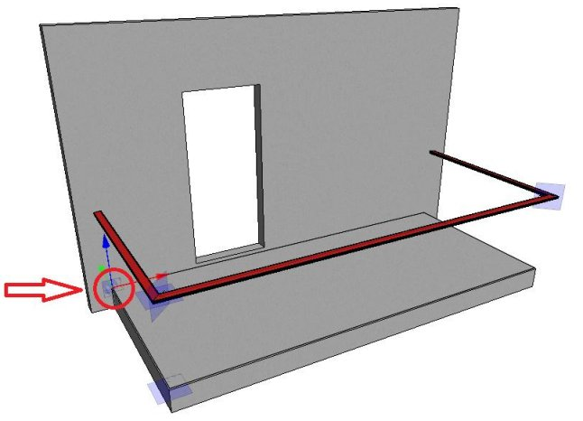
For example, feasible location of the origin. The figure below features a balcony railing and its reference model. The origin is in the place indicated in the figure.
- Create a new local assembly A.
- Create a new local part Jig in the local assembly.
- Create a New 3D Sketch.
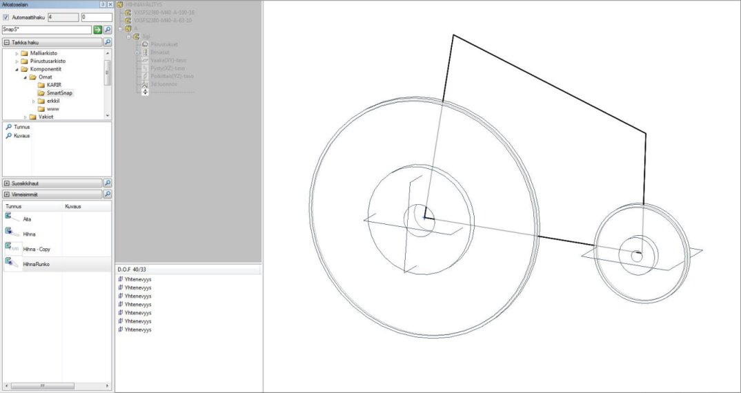
- Draw in the 3D sketch the necessary number of lines for positioning the assembly A, starting from the origin of the 3D sketch. Do not create constraints to other parts of the assembly at this stage. You can hide the other parts to ensure this. The constraints related to other parts are shown in the constraint tree in blue.
- Exit the 3D sketch.
- Restore the help planes of the part Jig.
- Exit the editing view of the part Jig.
- Exit the editing view of the assembly A.
- Release the assembly A.
Phase 2
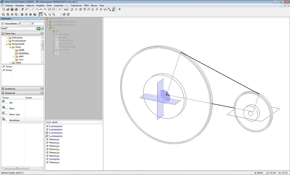
- Position the assembly A by adding constraints to the part Jig and the parts controlling the components in such a way that the assembly A is fully defined (the minus sign disappears from the tree).
- Fix the other parts if they have degrees of freedom.
- Conduct the positioning by using those elements of other parts whose purpose is to also control the part's geometry.
- Even if the assembly is fully defined, it is sometimes necessary to perform additional specification. For example, a non-driving distance constraint.
- Name the constraints in such a way that anyone using the same component will understand the purpose of each constraint. If several constraints are connected to the element of the same external part, assign the same name to each one of them.

Phase 3
- Select the part Jig in the pattern for editing.
- Edit the 3D sketch.
- Hide all other parts.
- Add the necessary number of lines.
- Add constraints from the lines to the parts help planes, if this is possible.
- Restore the parts that are required to define the constraints.
- Add constraints from the lines to the parts in such a way that the 3D sketch is fully defined.
- Name the constraints. If a constraint connected to the same element exists on the assembly plane, assign the same name to the 3D sketch constraints.
- Exit the part editing view.
- Save the model.
Phase 4
- Test the functionality of the Jig component with the Solve function. Change the shapes and locations of the controlling geometries. Click the Solve function again after the changes.
- If the result of the function is not what you wanted and the model breaks, open the saved model and attempt to repair it.
- The assembly constraints of an adaptive component may prevent changing other positions by dragging and dropping. If this is the case, add a suitable distance constraint and change the constraint value if necessary.
- Release the assembly A for editing.
- Hide all the other parts of the main assembly except A and Jig.
- Model the actual parts in the assembly A that their geometry is determined based on the part Jig.
- Once the component is finished and nothing is selected in the working window, select the context-sensitive function Save to Library in the assembly editing mode.
Note:
- You can save a component into the library, if it has the Jig part only. The component can be opened into its own model to continue the modeling without compromising the adaptiveness of the component.