
SmartSnap Components
Library
What are they?
SmartSnap components are parts or subassemblies for which the constraints controlling their position and shape have been defined in advance. These constraints are requested when the component is added to the assembly.
The idea of the SmartSnap components is that the component is bound to external geometry immediately upon bringing it into the assembly. This positions the component correctly and shapes it according to the reference geometry specified.
An adaptive component can be a part or an assembly.
For example:
- The end plate of an I profile, which must follow the location and size of the profile end.
- Belt drive between two pulleys.
- Railings, stairs (lengths, numbers of steps, automatically adjusting angles).
- Profile structure supports, wind girders, etc.
Routine design becomes significantly faster when basic constructions are modeled in the component library and they can be used anywhere.
Why use them?
Adaptive components are intended to facilitate design work by reducing the modeling work for similar frequently-used components.
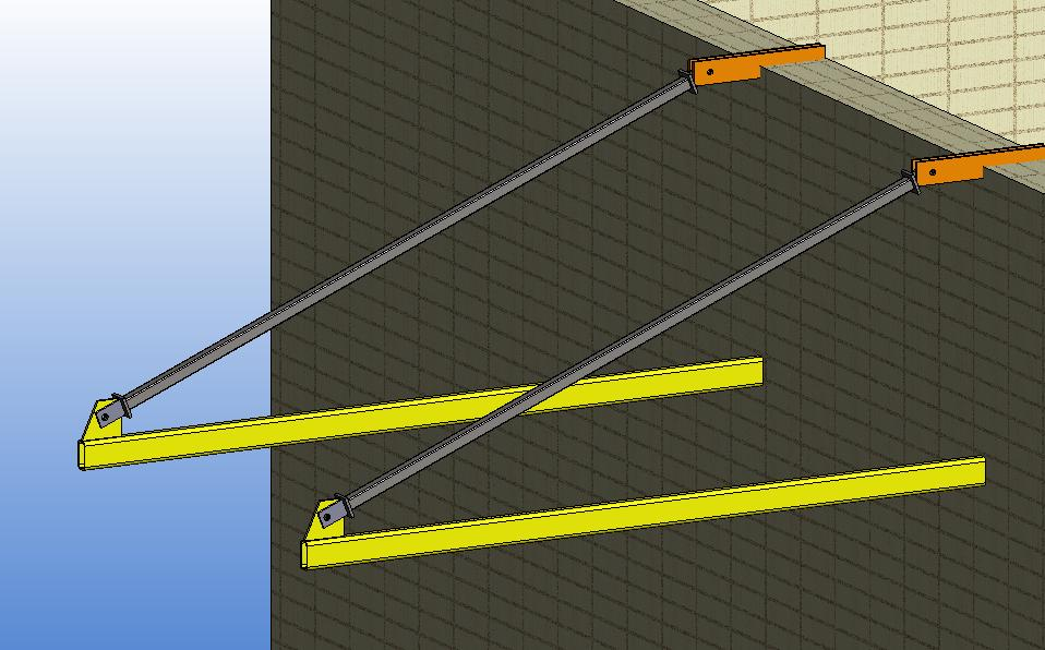
The supports in the figure can be modeled in the normal way, but positioning it as a SmartSnap component only takes a few mouse clicks. If you create a similar structure more than once, you will save over 90% of time.
An added benefit is that the structure is automatically adapted to the surrounding geometry. The component is easily modified if the surrounding geometry changes.
When to use them?
- The geometry of separate parts or parts under the geometry of a subassembly are determined, based on other parts of the geometry.
- Similar parts/subassemblies are used often but the shape is not always the same.
- It is always possible to find the elements (faces, lines or points) that control the component in the assemblies in which the component is intended to be used. For example, bicycle chains.
- The positioning of a subassembly in an assembly is always performed, based on similar elements, even if the geometry is not determined by the other parts.
- In this case, the component deviates from a conventional subassembly in that it prompts you for the elements that are required to position it when it is being brought into the assembly. For example, bicycle pedals.
How to use them?
-
The component is a part.
If the component is a part, add the constraints controlling the shape to the 3D sketch that is used as the first feature. Assembly constraints cannot be saved for the part. The position of the assembly cannot be defined.
-
The component is an assembly.
If the component is an assembly, add the constraints controlling the shape to the 3D sketch that is used as the first feature of the first part, and add the constraints controlling the position to the main level of the assembly.