
Drawing a Sketch of a Part Model on a Plane
2D elements are used to create sketches for feature modeling. The drawing functions are available in the sketching mode of a part model. The elements are drawn on the sketching face.
Drawing Tools
The rough shape of a part is created by drawing the first sketch in the sketching coordinate system so that it can easily be fixed to the axes or origin of the coordinate system.
Start creating the sketch by drawing the necessary line elements. We recommend drawing the sketch in approximately the correct proportions. The exact length of the line or the radius of the circle, for example, is significance in sketching. The exact size, direction and positioning of the elements in relation to each other can be determined using constraints.
The following element types are available for drawing:
- Two Points Line
- Arc by Selecting 2 Radius Points
- Arc by Selecting 3 Radius Points
- Construction Circle
- Ellipse Selecting Three Points
- Polyline
- Spline
- Curve Equation
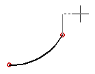
 After drawing a polyline, the program will highlight the open ends of lines with red points. If a polyline in a sketch is open, it can be used to create a guide curve. If you intend to use the polyline to some other function, such as extrusion, the polyline need to be closed. A polyline is closed when no red points are displayed on the lines.
When drawing lines, the following functions can be used to edit the lines:
- Round Two Sketch Lines
- Bevel Two Lines
- Trim Two Lines Together in a Sketch
- Trim a Line to Another Line in a Sketch
- Pattern
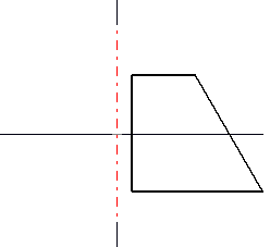
Draw the rotation axis and the rest of the sketch in the sketching coordinate system. The rotation axis has been drawn in the direction of the coordinate system axis, and the rest of the sketch in relation to it. The rotation axis is first drawn as a shape line and then determined as a rotation axis. The sketch is fixed to the axis of the sketching coordinate system using geometric constraints.
Lines from a 2D Drawing
You can copy lines from a 2D drawing and paste them into a sketch. Open the 2D drawing, select the lines to be copied and copy lines. Activate the sketching window and paste lines to the sketch. You can position the lines like a sketch imported from the library.
Line Properties
The lines in a sketch are drawn as shape lines. You can also draw construction lines in a sketch to facilitate drawing, and another necessary construction line, the rotation axis. The default line type is shape line. You can edit the line properties. Select the line(s) in the sketch and the  Properties.
Cursor
A sketch consists of various elements: points, lines and constraints. The cursor has the following properties when drawing:
- When snapping the cursor to an element, the appearance of the cursor will change near or at a point, line and constraint.
- When drawing a line, the cursor can be snapped to the line, a point on the line, the center point of the line, the center point of a circle/arc or the intersection point of circles.
- When drawing a line, the cursor will automatically be set as a ruler at 0, 45, 90, etc. degrees.
Editing a Sketch
The following functions can be used to edit the elements in a sketch:
- Copy, cut, paste, delete
- Undo, redo
- Drag line, point
- Drag entire sketch
- Edit sketch using dimension constraints
- Fix the line in the sketch by the F key, and release by the F key.
Adding Constraints to a Sketch
Geometric constraints are defined for the elements in a sketch in order to enable the editing of the sketch using dimension constraints. The available constraints for the elements include dimensions and geometric constraints like parallel, tangential, concentric, etc. The constraints can be used to control the size, direction and position of the elements in relation to each other.
 Define Constraints in a Sketch
Connect a Sketch
You can fix a sketch to the axes or origin of the sketching coordinate system using geometric constraints. For example, the sketch line can be coincident with the axis of the coordinate system, and you can define the distance between the line and the origin, etc.
When adding a finished sketch from the library to the reference face of a part, for example, it is positioned using its origin. Positioning the sketch using geometric constraints is important, as it will insure that the correct position of the sketch is retained later when editing the geometry of the part using the dimension table.
You can fix a sketch to the sketching coordinate system by making the rotation axis coincident with the vertical axis of the coordinate system. The rest of the sketch is determined using dimension constraints in relation to the rotation axis.

Saving a Sketch in the Sketch Library
The sketches in the sketch library can be used to model several different models. Sketches that are frequently used to model parts or sheet-metal parts can be saved in the sketch library. When creating the sketch note that the sketch have to position easily to it position, and its geometry must can be editable. An existing sketch opened from the sketch library can be positioned using its origin. You can edit the geometry of the sketch using the variable values of dimension constraints.